Actuator and robot arm apparatus
A technology of robot arm and transmission device, applied in the direction of manipulator, electromechanical device, measuring device, etc., can solve the problem of heavy configuration and achieve the effect of safe driving
Active Publication Date: 2016-10-26
SONY CORP
View PDF9 Cites 19 Cited by
- Summary
- Abstract
- Description
- Claims
- Application Information
AI Technical Summary
Problems solved by technology
Therefore, it is possible to make
Method used
View moreImage
Smart ImageViewing Examples
Examples
 PUM
 Abstract
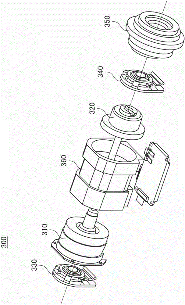
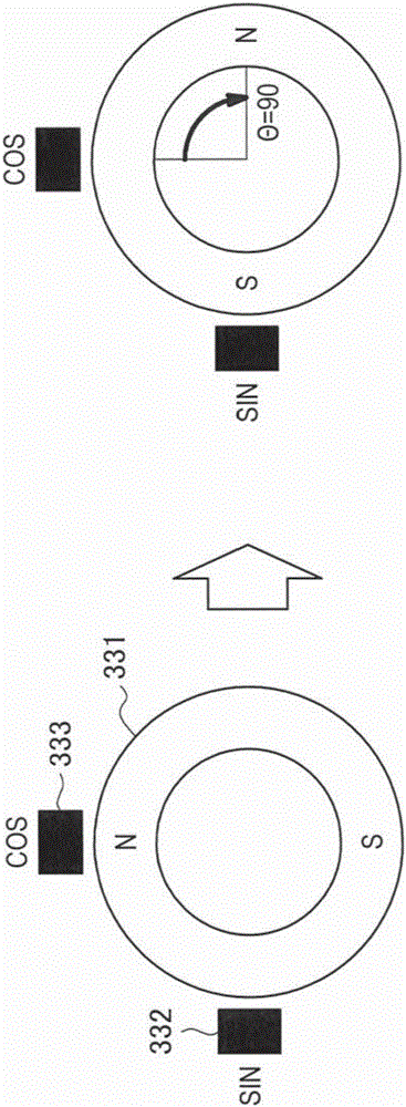
To make it possible to highly accurately detect a rotation angle and to drive more safely. Provided is an actuator (300) that is provided with: a reduction gear (320), which reduces, at a predetermined reduction ratio, a rotation speed of an input shaft connected to a rotation shaft of a motor (360), and which transmits the rotation speed to an output shaft (350); a first absolute angle encoder (330) that detects a rotation angle of the input shaft; and a second absolute angle encoder (340) that detects a rotation angle of the output shaft.
Description
technical field [0001] The present disclosure relates to a transmission device and a robot arm device. Background technique [0002] A rotary encoder (hereinafter also simply referred to as an encoder) is widely used as a sensor device for detecting the rotation angle of a rotary driven member, such as an automotive power steering device or a joint unit of a robot device. In rotation angle detection using an encoder, various techniques have been proposed to further improve detection accuracy. [0003] For example, Patent Document 1 discloses a technology that converts the rotation of the main rotation shaft into the rotation of two detection shafts through reduction gears having different reduction ratios, detects the rotation angle of each detection shaft with a corresponding encoder, and The absolute angle of the main rotation shaft is calculated based on the difference between the detected rotation angles, thereby accurately detecting the rotation angle of the main rotat...
Claims
Login to View More Application Information
Patent Timeline
 IPC IPC(8): H02K7/116H02K11/215B25J9/06B25J9/12B25J9/16B25J13/08G01D5/04G01D5/14G01D5/245H02P6/16
CPCB25J9/06B25J9/126B25J9/1641B25J13/088G01D5/04G01D5/145G01D5/2451G05B2219/39191H02K7/116H02K11/215H02P6/16
Inventor 小久保亘笠井荣良神川康久黑田容平坪井利充福岛哲治松田康宏宫本敦史
Owner SONY CORP
Features
- R&D
- Intellectual Property
- Life Sciences
- Materials
- Tech Scout
- Unparalleled Data Quality
- Higher Quality Content
- 60% Fewer Hallucinations
Learn More Browse by: Latest US Patents, China's latest patents, Technical Efficacy Thesaurus, Application Domain, Technology Topic, Popular Technical Reports.
© 2025 PatSnap. All rights reserved.Legal|Privacy policy|Modern Slavery Act Transparency Statement|Sitemap|About US| Contact US: help@patsnap.com


