Antenna

An antenna and wire structure technology, applied in the field of communication, can solve the problems of large size and narrow antenna bandwidth, and achieve the effect of high broadband profile and low profile

Active Publication Date: 2016-10-26
TONGYU COMM INC
View PDF11 Cites 4 Cited by
  • Summary
  • Abstract
  • Description
  • Claims
  • Application Information

AI Technical Summary

Problems solved by technology

[0003] The object of the present invention is to provide an antenna to solve the problem of narrow bandwidth and large size of the antenna in the prior art

Method used


Image

  • Antenna
  • Antenna
  • Antenna

Examples


Embodiment Construction

[0024] In order to enable those skilled in the art to better understand the technical solution of the present invention, an antenna provided by the present invention will be further described in detail below in conjunction with the drawings and specific embodiments.

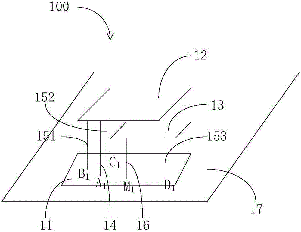
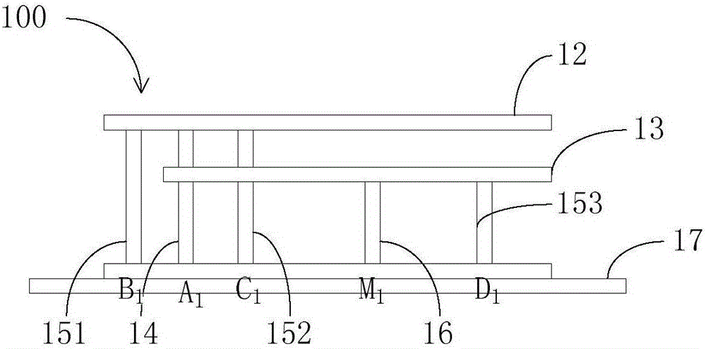
[0025] See first figure 1 and figure 2 , figure 1 is a schematic diagram of a three-dimensional structure of an embodiment of the antenna of the present invention, figure 2 yes figure 1 A front view of an embodiment of the antenna of the present invention is shown.

[0026] The antenna 100 in this embodiment includes a feed network layer 11 , a radiation layer 12 , and a parasitic layer 13 located between the feed network layer 11 and the radiation layer 12 .

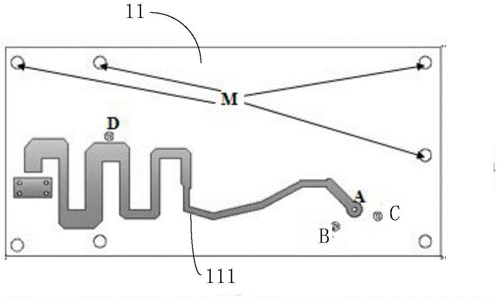
[0027] see image 3 , image 3 yes figure 1 A schematic diagram of the structure of the feed network layer in an embodiment of the antenna shown, image 3 The middle feed network layer 11 includes a wiring structure 111 and a plurality of metal p...


PUM


Abstract

The invention discloses an antenna which comprises a feed network layer, a radiation layer, and a parasitic layer which is arranged between the feed network layer and the radiation layer. The feed network layer comprises a wiring structure and a plurality of metal points. The radiation layer is provided with a first radiation fin. The first radiation fin is electrically connected with the wiring structure through a feed column. The first radiation fin is electrically connected with a first metal point in the plurality of metal points through a first conductive column. The parasitic layer is connected with a second metal point in the plurality of metal points through a second conductive column. The wiring structure is wave-shaped. The first radiation fin is provided with an opening. The antenna of the invention has advantages of high bandwidth and low profile.

Description

technical field [0001] The invention relates to the technical field of communications, in particular to an antenna. Background technique [0002] Antennas are the main components for communication, and antennas with different characteristics need to be used for different frequency bands. For example, for the mobile communication band GSM 900 with a lower frequency (698-960MHz), if a half-wave vibrator antenna is used, its size is relatively large, which limits its scope of use; if a microstrip half-wave patch antenna is used , there is also the problem of large size; if a PIFA antenna with a small size is used, its bandwidth will be narrow and it will not be able to cover all the frequency bands of GSM 900. Contents of the invention [0003] The object of the present invention is to provide an antenna to solve the problems of narrow bandwidth and large size of the antenna in the prior art. [0004] In order to solve the above problems, the present invention proposes an a...

Claims


Application Information

Patent Timeline
Patent Type & Authority Applications(China)
IPC IPC(8): H01Q1/36H01Q1/50
CPCH01Q1/36H01Q1/50
Inventor 汪常娥高文成梁承献吴中林刘木林任军飞
Owner TONGYU COMM INC
Why Eureka
Try Eureka