
Airspace coordinate correction method for three-coordinate measuring machine based on multi-station measurement of laser tracking instrument

A three-coordinate measuring machine and laser tracker technology, which is applied in the field of precision measurement technology and coordinate measurement, can solve problems such as difficulty in improving the accuracy of laser tracking systems

Active Publication Date: 2016-10-26
BEIJING UNIV OF TECH
View PDF6 Cites 25 Cited by
  • Summary
  • Abstract
  • Description
  • Claims
  • Application Information

AI Technical Summary

Problems solved by technology

In the calibration of the three-coordinate measuring machine using the laser tracker, although only the precision interferometric length measurement of the laser tracker combined with the multi-station measurement method is used, the three-dimensional spherical coordinate measurement of the laser tracker is not used, but due to the traditional commercial The limitation of the mechanical structure of the laser tracker makes it difficult to improve the accuracy of the traditional laser tracking system

Method used


Image

  • Airspace coordinate correction method for three-coordinate measuring machine based on multi-station measurement of laser tracking instrument
  • Airspace coordinate correction method for three-coordinate measuring machine based on multi-station measurement of laser tracking instrument
  • Airspace coordinate correction method for three-coordinate measuring machine based on multi-station measurement of laser tracking instrument

Examples


Embodiment Construction

[0072] The present invention will be further described in detail below in conjunction with the accompanying drawings, so that those skilled in the art can implement it with reference to the description.

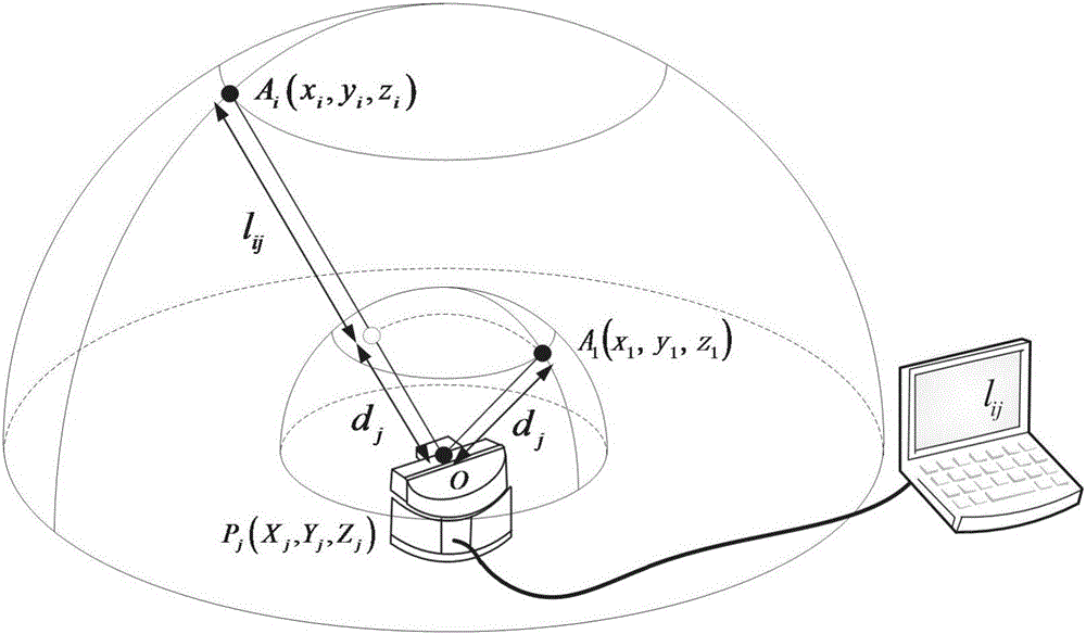
[0073] used in the experiment as Figure 4 The CMM laser tracker multi-station measurement system shown is used to measure the relative interferometric length measurement, so the analysis is carried out through the following steps:

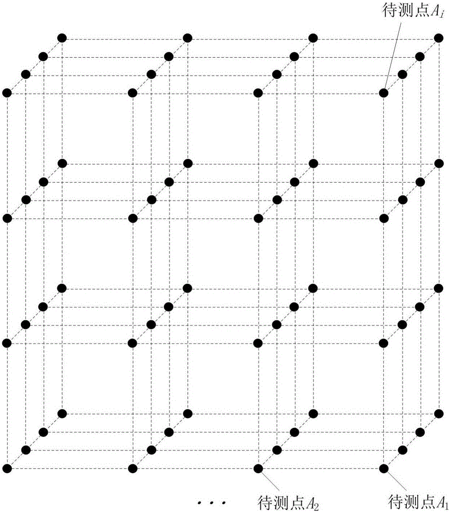
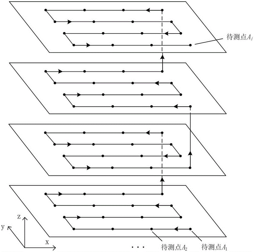
[0074] Step 1: Construct the multi-site measurement model of the laser tracker. Considering the measurement accuracy and the time required for the experiment, the number of laser tracker stations is determined to be 5, and the 5 stations are not in the same plane. The number of space to-be-measured points in the CMM coordinate system is 4×4×4=64, and the number of measured points at the same height is 4×4=16.

[0075] Step 2: Divide the measurement space and determine the coordinates of 64 points to be measured. The corresponding coordinates ar...


PUM


Abstract

The invention discloses an airspace coordinate correction method for a three-coordinate measuring machine based on multi-station measurement of a laser tracking instrument. The method comprises the steps of firstly, dividing measuring point grids within the measuring space range of the three-coordinate measuring machine, determining measuring point coordinates, moving a target mirror to each measuring point during measuring, and performing, by the laser tracking instrument, station transfer measurement beyond the grid space range to acquire a relative interference length measurement value from each measuring point to a first measuring point under different stations; secondly, solving the coordinates of each station and the distance between the corresponding station and the first measuring point by using a two-point distance formula and the principle of least square method; thirdly, solving the correction value of each measuring point via an interference length measurement error equation by using the coordinates of each station, the measuring point coordinates and the distance between each station and the first measuring point; fourthly, acquiring more accurate measuring point correction values by adopting an iteration method for improving the station coordinate precision and the distance precision from the stations to the first measuring point; and finally, acquiring the correction value of any measuring point within the grid space by using a trilinear interpolation method, thereby improving the measuring precision of the three-coordinate measuring machine.

Description

technical field [0001] The invention relates to an analysis method for improving the measurement accuracy of a Coordinate Measuring Machine (CMM), in particular a method for correcting airspace coordinates of a Coordinate Measuring Machine based on multi-station measurement of a laser tracker, which belongs to precision measurement technology and coordinate The field of measurement technology. Background technique [0002] As a high-efficiency precision measurement system in coordinate measurement technology, the three-coordinate measuring machine plays an increasingly important role in modern manufacturing and aviation, aerospace and other fields because of its high measurement accuracy, fast speed, and strong flexibility. It is the key basic measurement equipment in the field of advanced manufacturing, and also the key testing equipment for quality inspection and control in civil industry production. It can complete the spatial three-dimensional coordinate measurement of g...

Claims


Application Information

Patent Timeline
Patent Type & Authority Applications(China)
IPC IPC(8): G01B11/00
CPCG01B11/005G01B21/045
Inventor 陈洪芳郑博文石照耀孙衍强
Owner BEIJING UNIV OF TECH
Learn More