Method for installing stiffening beam of suspension bridge over navigable river and swing shift system used in method

An installation method and technology for suspension bridges, applied in the field of swaying systems, can solve problems such as poor economy and operating efficiency, long construction period of suspension bridges, and huge structural system, and achieve the effects of shortening the construction period, low cost, and good economy

Active Publication Date: 2016-10-26
DEYANG TIANYUAN HEAVY IND
View PDF6 Cites 7 Cited by
  • Summary
  • Abstract
  • Description
  • Claims
  • Application Information

AI Technical Summary

Problems solved by technology

Whether it is walking jacking equipment or spanning cable crane, its structural system is huge and complex, with long construction period and high construction cost, which makes the suspension bridge built by such technical measures have long construction period, high input cost, economical and Poor operating efficiency

Method used


Image

  • Method for installing stiffening beam of suspension bridge over navigable river and swing shift system used in method
  • Method for installing stiffening beam of suspension bridge over navigable river and swing shift system used in method
  • Method for installing stiffening beam of suspension bridge over navigable river and swing shift system used in method

Examples


Embodiment Construction

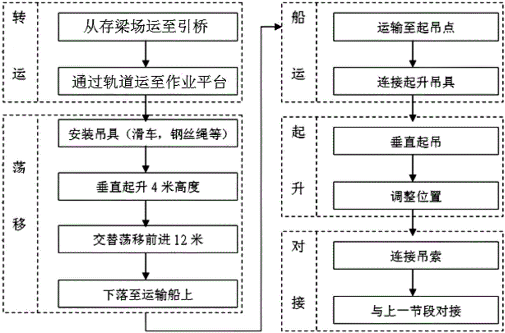
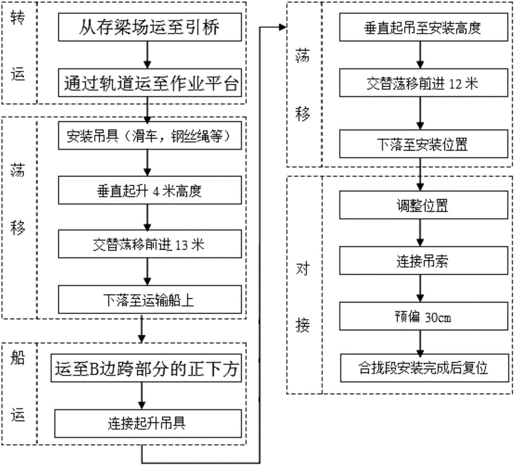
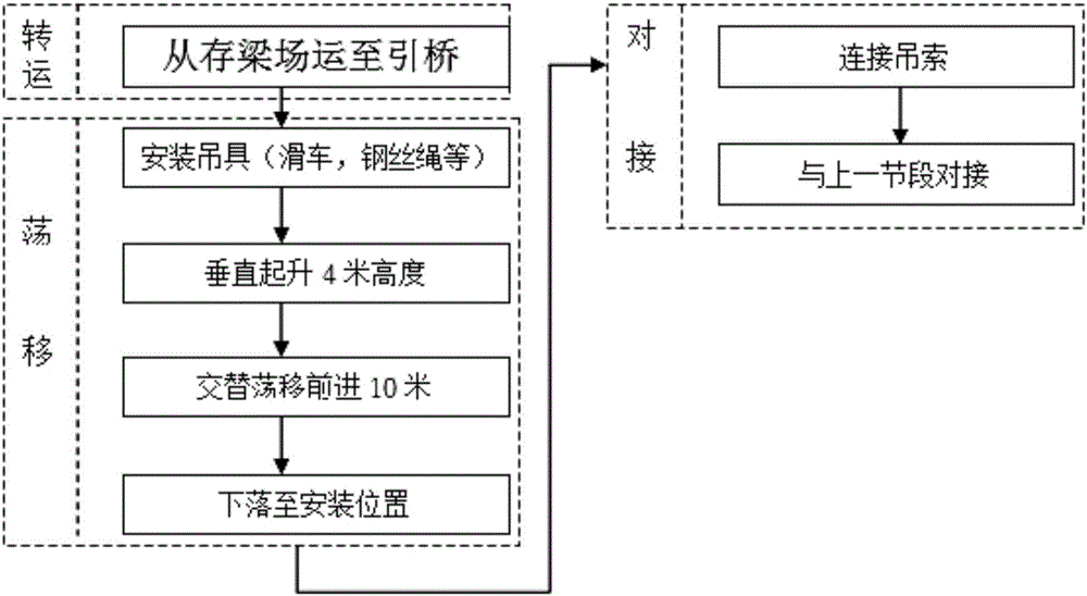
[0034] The invention relates to a method for installing a stiffening beam of a suspension bridge on a river.

[0035] Among them, the stiffening beam of the suspension bridge is usually mainly composed of the main truss, the upper and lower parallel, and the transverse truss. The stiffened beam adopts integral node technology, and each member of the stiffened beam is a factory weldment. In order to reduce the on-site assembly and connection of the stiffened beam members, the chord and one or two nodes are welded into a whole in the factory, and high-strength bolts are used on site. Connected into trusses. The stiffening beams of the whole bridge are divided into dozens of sections, and the weight of each section is as high as tens of tons; the stiffening beams of each section are usually assembled in the assembly yard of the construction site.

[0036] The river targeted by the present invention is a river with navigable capability.

[0037] The design structure of the suspe...


PUM


Abstract

The invention discloses a method for installing a stiffening beam of a suspension bridge over a navigable river and a swing shift system used in the method. The suspension bridge is an earth-anchored suspension bridge of a two-tower three-span structure and comprises a main tower A, a main tower B, a side span part A, a side span part B and a middle span part, and a beam storage yard is arranged at the position, on one side of the main tower A, of a shore base. The installation method includes the following steps that a plurality of winches are arranged at the top of the main tower A and the top of the main tower B respectively, an approach bridge is erected between the beam storage yard and the main tower A, a work platform communicated with the approach bridge is erected on the surface, back on to the approach bridge, of the main tower A, and a transport ship is prepared on the river; the middle span part, the side span part B and the side span part A are installed in sequence, wherein the middle span part is installed in the sequence of approach bridge transport, swing shift lowering, ship transport and lifting connection, the side span part B is installed in the sequence of approach bridge transport, swing shift lowering, ship transport, lifting swing shift and combination connection, and the side span part A is installed in the sequence of approach bridge transport, swing shift positioning and combination connection.

Description

technical field [0001] The invention relates to the engineering construction of a suspension bridge, in particular to a method for installing a stiffening beam of a suspension bridge on a navigable river, and a swinging system used in the installation method. Background technique [0002] Suspension bridge is a bridge with the main cable bearing the tension as the main load-bearing component. 1. It is composed of a sling hanging from the main cable through cable clamps and a bridge deck system connected to the sling. It has the characteristics of low material consumption, light weight, and large spanning capacity. The deck system of a suspension bridge is mainly composed of a stiffening beam bearing load, a bridge deck laid on the stiffening beam and other deck systems, and the stiffening beam of a bridge deck system is mainly composed of multiple stiffening beam segments spliced ​​in sequence. Usually, each stiffening beam segment is more than two meters high, more than te...

Claims


Application Information

Patent Timeline
Patent Type & Authority Applications(China)
IPC IPC(8): E01D21/00E01D11/02
CPCE01D11/02E01D21/00
Inventor 王东明涂小东
Owner DEYANG TIANYUAN HEAVY IND
Why Eureka
Try Eureka