Withdrawing type coiling module

A pull-out and coiling technology, applied in the field of pull-out coiling modules, can solve the problems of unsmooth retraction and pull-out of the wire, large thickness, etc., and achieve the advantages of stretching and recycling, low resistance, and smooth rolling. Effect

Active Publication Date: 2016-10-26
QINGDAO GOERTEK
View PDF10 Cites 6 Cited by
  • Summary
  • Abstract
  • Description
  • Claims
  • Application Information

AI Technical Summary

Problems solved by technology

[0004] In view of the above problems, the present invention provides a pull-type wire winding module to solve the problems that the existing pu...

Method used


Image

  • Withdrawing type coiling module
  • Withdrawing type coiling module
  • Withdrawing type coiling module

Examples


Embodiment 1

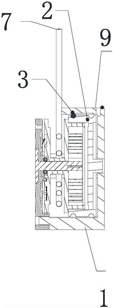
[0034] Such as Figure 1 to Figure 3 As shown together, the embodiment of the present invention provides a pull-type wire winding module, which is provided with a rotating wheel 6, which can rotate around the rotating shaft 8, the rotating wheel 6 is connected with a coil spring 5, and the wire 7 is wound on the rotating wheel 6 On the top, a stop mechanism is provided in cooperation with the runner 6, the stop mechanism includes a functional track, a ball 3 and a rolling auxiliary device, the functional track includes a locking track connected to the combination, a communication track 25 and a circular track (21, 22), three All these tracks are grooved and arranged around the outer circumference of the runner 6 (the track needs to be set by means of the cover 2), and balls 3 are arranged in the functional track. In the embodiment of the present invention, the track is arranged around the outer circumference of the runner 6. Compared with the track being arranged on the end fa...

Embodiment 2

[0054] The difference between the second embodiment of the present invention and the first embodiment is that the runner 6 is sheathed with a track wheel, and three kinds of tracks are arranged on the outer circumference of the track wheel, and the track wheel and the runner 6 are clipped together, and can Rotate together with runner 6.

[0055] The rest of the structure of Embodiment 2 of the present invention is similar to that of Embodiment 1, and will not be repeated here.

Embodiment 3

[0057] The difference between this embodiment and Embodiment 1 and Embodiment 2 is that the three kinds of tracks are directly arranged on the outer circumferential surface of the runner 6, and there is no need to use other components to set the tracks, but the number of runners 6 should be appropriately increased. radial thickness, and to avoid conflict between the track and the cover structure of the coil spring placement slot. This design can further reduce the radial dimension of the winding module.

[0058] The rest of the structure of this embodiment is similar to that of Embodiment 1, and will not be repeated here.


PUM


Abstract

The invention discloses a withdrawing type coiling module which is provided with a runner; the runner is provided with a coil spring; a guide line is twined on the runner; a stop motion mechanism is arranged in a manner of being matched with the runner and comprises a functional rail, a ball and a rolling auxiliary device; the functional rail comprises a locking rail, a communicating rail and an annular rail which are connected and combined; the three types of rails take the shape of grooves and are arranged around the periphery of the runner; a guide groove is formed in the rolling auxiliary device; two ends of the guide grooves are arranged on the upper side and the lower side of the periphery of the runner respectively; the guide groove and the functional rail are matched to clamp the ball; and along with rotation of the runner, the ball rolls in the functional rail to carry out rotary locking or rotary unlocking on the runner. According to the invention, the rails are arranged around the periphery of the runner, so that the thickness of the coiling module is decreased in the direction of a rotary shaft, and the withdrawing type coiling module is suitable for being used on a product with a smaller thickness requirement.

Description

technical field [0001] The invention relates to a pull-type wire winding module, in particular to a stop mechanism of a pull-type wire winding module. Background technique [0002] Auxiliary devices equipped with wires are used in many electronic devices, such as earphones, mice, keyboards and the like. In order to be more convenient to use, more and more wire winding modules are designed in these auxiliary devices to accommodate wires or signal wires. The wire winding module is usually equipped with a wheel, a coil spring and a stop mechanism. The wire is wound on the wheel, and the wire can be automatically retracted under the action of the elastic restoring force of the coil spring. During the retraction process, the stop mechanism can stop the rotation. The wheel rotates to prevent the retracting action of the runner, so that the wire of an appropriate length can be reserved and not retracted. [0003] There are many types of stop mechanisms in the prior art, one of wh...

Claims


Application Information

Patent Timeline
IPC IPC(8): B65H75/38B65H75/44B65H75/48
CPCB65H75/38B65H75/4418B65H75/486B65H2701/3919B65H75/4434B65H75/4471B65H75/4442B65H75/4402
Inventor 唐明军
Owner QINGDAO GOERTEK
Why Eureka
Try Eureka