Staggered discharge device of medical parts

A technology for discharging devices and accessories, which is applied to conveyor objects, transportation and packaging, conveyors, etc., can solve problems such as inability to detect, and achieve the effects of improving reliability, increasing quantity, and speeding up labor productivity.

Inactive Publication Date: 2016-10-26
梁启明
View PDF8 Cites 9 Cited by
  • Summary
  • Abstract
  • Description
  • Claims
  • Application Information

AI Technical Summary

Problems solved by technology

[0004] However, although the above-mentioned feeding device also uses dislocation to increase the number of feeding accessories, it cannot detect that each carrier contains accessories during each feeding process, and there are loopholes in the delivery of medical accessories

Method used


Image

  • Staggered discharge device of medical parts
  • Staggered discharge device of medical parts
  • Staggered discharge device of medical parts

Examples


Embodiment 1

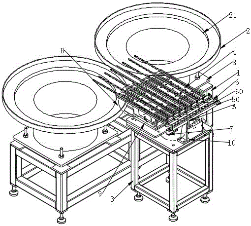
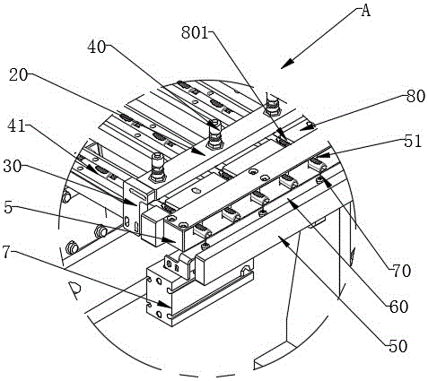
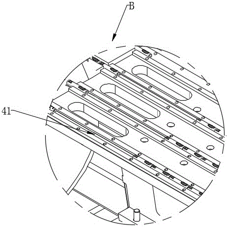
[0059] figure 1 It is a structural schematic diagram of an embodiment of a dislocation discharging device for medical accessories in the present invention; figure 2 for figure 1 Partial enlarged view of part A in middle; image 3 for figure 1 Partial enlarged view of part B in ; figure 1 , figure 2 as well as image 3 As shown, the dislocation discharge device for medical accessories provided in this embodiment is used as a delivery device for medical accessories for safety venous needles. The dislocation discharge device includes: a vibration unit, a flat delivery unit, a dislocation unit and an optical fiber detection unit .

[0060] In this embodiment, the position of the vibrating plate support 1 is defined as the rear of the dislocation discharge device; the position of the horizontal feeding support 3 is defined as the front of the dislocation discharge device.

[0061] Specifically, the horizontal delivery unit is located between the vibration unit and the disp...

Embodiment 2

[0087] Figure 20 It is a schematic structural diagram of Embodiment 2 of a dislocation discharge device for medical accessories; Figure 20 As shown, the dislocation discharge device also includes an adjustment unit, and the adjustment unit is connected with the dislocation unit to adjust the spatial position of the dislocation unit, so that the input port of the medical accessories on the dislocation unit is opposite to the output port of the medical accessories on the flat delivery unit together.

[0088] The dislocation feeding device provided in this embodiment pushes the dislocation movable plate 5 through the dislocation cylinder 7, so that the odd-numbered square grooves 51 and the even-numbered square grooves 51 on the dislocation movable plate 5 are respectively connected with the strips on the flat feeding base plate 4 in sequence. The rectangular groove 41 is connected to increase the quantity of accessories feeding, and at the same time, the optical fiber sensor ...


PUM


Abstract

The present invention discloses a staggered discharge device of medical parts. The staggered discharge device comprises a vibrating unit, a flatwise conveying unit and a staggering unit, wherein the flatwise conveying unit is disposed between the vibrating unit and the staggering unit, the medical parts in the vibrating unit enter into the flatwise conveying unit in turn and are conveyed into the staggering unit through the flatwise conveying unit, and an optical fiber detection unit is installed on the staggering unit and is used for detecting if any medical parts stay in square grooves in the staggering unit. According to the staggered discharging device provided by the invention, a staggered moving plate is pushed by a staggered cylinder to enable the square grooves at the n-th (n being an odd number) positions of the staggered moving plate and the square grooves at the i-th (i being an even number) positions of the staggered moving plate to be communicated with strip-shaped grooves in flatwise conveying bottom plates in turn, thereby increasing the loaded parts; and through optical fiber sensors, the number of the parts maintains the same every time the parts are loaded, the reliability of a material loading device is improved, and the labor productivity is promoted.

Description

technical field [0001] The invention belongs to the technical field of medical device manufacturing equipment, and in particular relates to a dislocation discharging device for medical accessories. Background technique [0002] There are many kinds of medical accessories. For example, the infusion set is an auxiliary device commonly used in medical treatment. It is mainly used for intravenous infusion. It is an important disposable medical consumable that has undergone aseptic treatment and establishes a channel between the vein and the liquid. The medical accessories assembled into an infusion set include an intravenous needle, a protective cap, a liquid medicine filter, a regulator for controlling the flow rate of the liquid medicine, a drip pot, a bottle stopper piercer, an air filter for an air intake tube, etc. All medical accessories are connected through conduits, and the medicinal liquid flows through the conduits. Among them, the regulator can adjust different liqu...

Claims


Application Information

Patent Timeline
Patent Type & Authority Applications(China)
IPC IPC(8): B65G27/02B65G47/14B65G47/32B65G47/82
Inventor 梁启明
Owner 梁启明
Why Eureka
Try Eureka