Chip collection and removal trolley and use method thereof
A small trolley and row collection technology, which is applied in the direction of trolleys, multi-axis trolleys, trolley accessories, etc., can solve the problems of inconvenient use and complex structure, and achieve the effects of easy turning, improved spring pressing effect, and convenient operation
- Summary
- Abstract
- Description
- Claims
- Application Information
AI Technical Summary
Problems solved by technology
Method used
Image


Examples
Embodiment 1
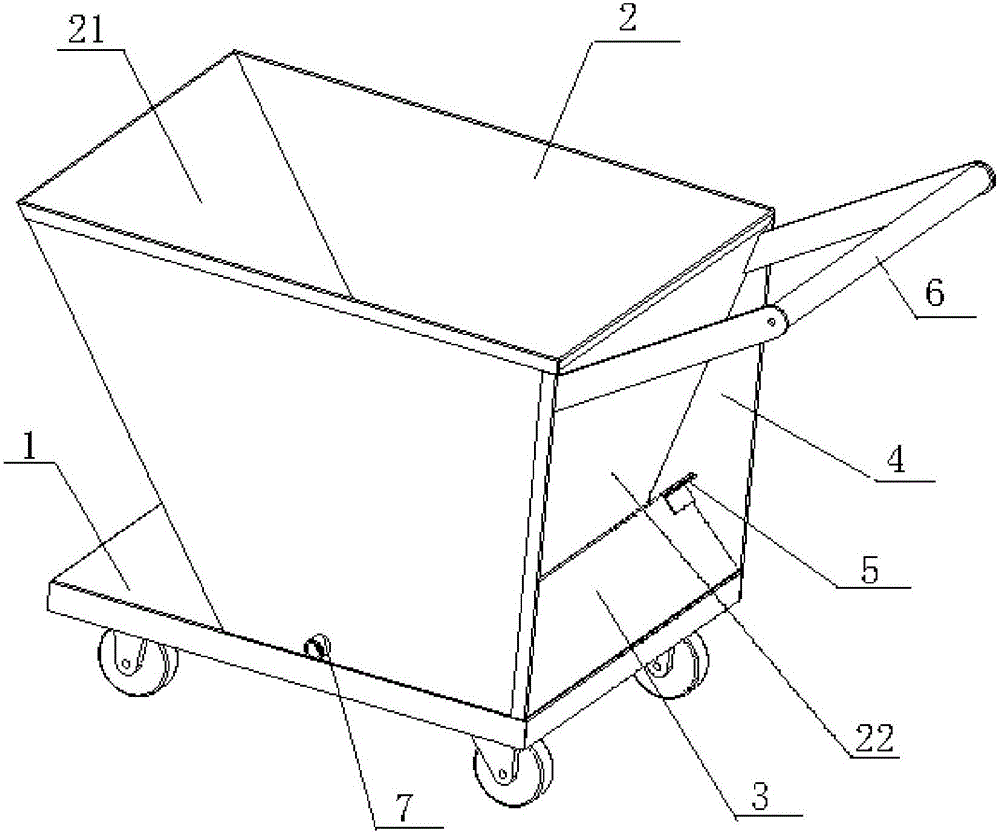
[0044] like figure 1As shown, a kind of chip-collecting trolley of this embodiment includes a flatbed vehicle surface 1 and a hopper 2, and also includes an elastic pressing plate 3 and a wing plate 4; the hopper 2 is a trapezoidal body with a large opening and a small bottom surface, including 1. The front plate 21 and the rear plate 22 which are inclined inwardly and gradually closed, and two side plates 23 perpendicular to the flatbed vehicle surface 1, wherein: the front plate 21 is connected with the flatbed vehicle surface 1 in an overturned manner; the bottom end of the elastic pressure plate 3 is connected to the flatbed vehicle The tail end of the surface 1 is connected by elastic pressure reset; there are two wing plates 4, which are the backward extending plates of the two side plates 23, protruding from the slope formed by the rear plate 22, and the inner sides of the two wing plates 4 are relatively symmetrically arranged. The positioning block 5 and the elastic p...
Embodiment 2
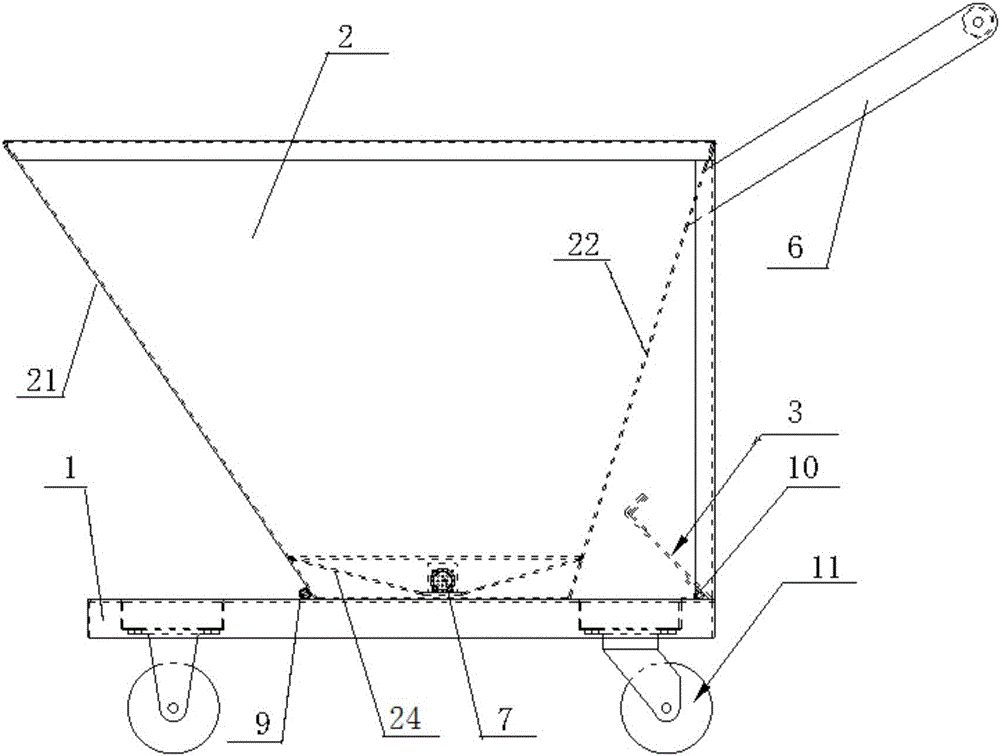
[0047] The basic structure of the chip-collecting trolley of this embodiment is the same as that of Embodiment 1, and the improvements are as follows: figure 2 and 3 As shown, the front panel 21 is connected to the flatbed vehicle surface 1 through a hinge hinge 9; Such as Figure 5 As shown, the spring 10 is a torsion spring, and the elastic pressing rods at both ends extend obliquely at an acute angle. The upper elastic pressing rod 101 is fixedly connected to the elastic pressing plate 3; the lower elastic pressing rod 102 is fixedly connected to the flatbed vehicle surface 1; Face 1 upper surface.
[0048] A method of using a chip collection trolley in this embodiment, the steps are:
[0049] A. Chip collection: push the trolley to the bottom of the discharge port of the chip conveyor to collect the chips of the machine tool;
[0050] B. Chip transportation: after the collection is full, replace another small trolley to pick up the material, pull the small trolley ful...
Embodiment 3
[0056] The basic structure of this embodiment is the same as that of embodiment 2, except that it also includes a frame-shaped push-pull rod 6, the fixed end of which is fixed on the upper part of the rear plate 22. The upper elastic pressing bar 101 and the lower elastic pressing bar 102 are all inwardly folded at a right angle to form a folding bar; the wing plate 4 is a right-angled triangular plate; The angle formed by the front plate 21 and the flat vehicle surface 1 is 30 degrees, and the angle formed by the rear plate 22 and the flat vehicle surface 1 is 80 degrees.
[0057] The chip collection and removal trolley of this embodiment is suitable for chips with a density of 5.0 to 5.5 after calculation. The steps for use are as follows:
[0058] A. Chip collection: push the trolley to the bottom of the discharge port of the chip conveyor to collect the chips of the machine tool;
[0059] B. Chip transportation: after the collection is full, replace another small trolley ...
PUM
 Abstract
Description
Claims
Application Information
 - R&D
- Intellectual Property
- Life Sciences
- Materials
- Tech Scout
- Unparalleled Data Quality
- Higher Quality Content
- 60% Fewer Hallucinations
Browse by: Latest US Patents, China's latest patents, Technical Efficacy Thesaurus, Application Domain, Technology Topic, Popular Technical Reports.
© 2025 PatSnap. All rights reserved.Legal|Privacy policy|Modern Slavery Act Transparency Statement|Sitemap|About US| Contact US: help@patsnap.com