
Method for printing a printed image on an object

A technology for printing images and objects, applied in printing, copying/marking methods, typewriters, etc., to achieve the effect of fine positioning

Active Publication Date: 2016-10-26
HEIDELBERGER DRUCKMASCHINEN AG
View PDF9 Cites 3 Cited by
  • Summary
  • Abstract
  • Description
  • Claims
  • Application Information

AI Technical Summary

Problems solved by technology

The printing device must be reset on the body

Method used


Image

  • Method for printing a printed image on an object
  • Method for printing a printed image on an object

Examples


Embodiment Construction

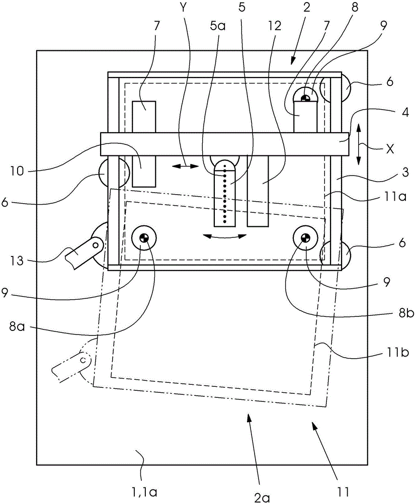
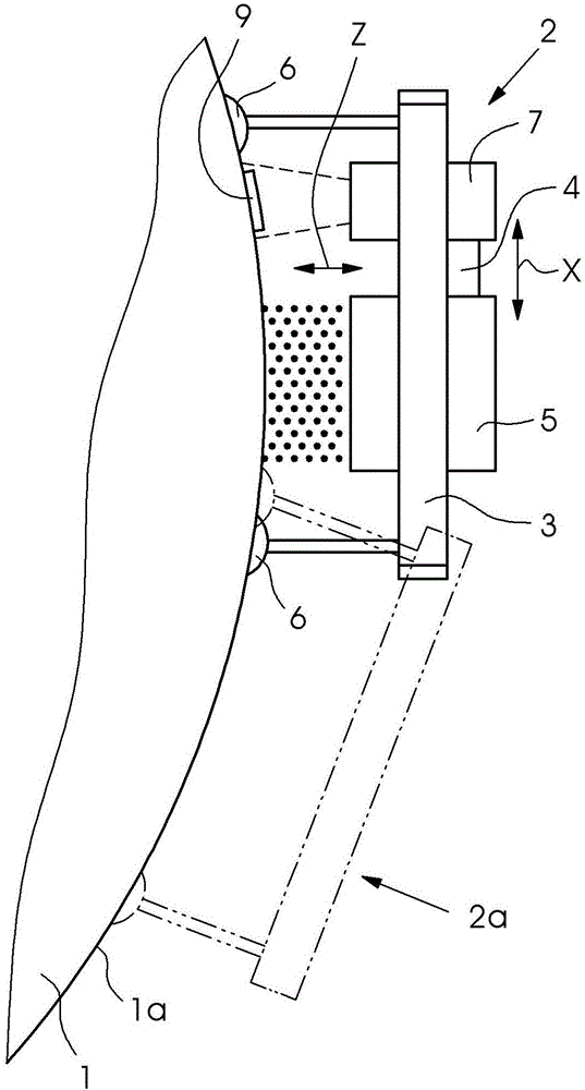
[0037] figure 1 A first view (from the Z direction) of a three-dimensional object 1 and a printing device 2 arranged on the three-dimensional object is shown while carrying out the method according to the invention. The object has a surface 1a that is not flat but curved. For example, a section of an aircraft fuselage may be involved.

[0038] The printing device 2 comprises a frame 3 and a crossbar 4 movable on the frame 3 in the X direction. The inkjet print heads 5 are arranged on this bar so as to be movable in the Y direction. The print head can also be oscillated in direction α (in the Z direction about an axis perpendicular to the X-Y plane) to orient the nozzle row 5a relative to the track to be printed during the printing movement (X and / or Y direction) (in particular oriented vertically), or to print tracks that do not extend parallel to the frame and / or the crossbar, or to be able to print in the edges.

[0039] The printing device is arranged with three suction...


PUM


Abstract

The present invention relates to a method for printing a printed image on an object, such as a vehicle body. An ink-jet printing apparatus (2) having at least one ink-jet printing head (5) is used, and the ink-jet printing apparatus is controlled by the data of the printed image (11). The method comprises following steps; printing a first region of the printed image (11):installing at least two self-adhesive labels(8,8a,8b) on the object (1); the label (9) is printed with reference information (8, 8a, 8b), preferably by means of said print head (5);the printing apparatus (2) is reset and roughly positioned and / or roughly orientated; the reference information (8, 8a, 8b) is detected, preferably by means of a camera (7); the printing apparatus (2), the printing head (5) and the printed image (11)and / or data are fine positioned and / or fine orientated by means of the reference information (8, 8a, 8b); and printing a second region (11b) of the printed image.

Description

technical field [0001] The invention relates to a method for imprinting a printed image on an object with the features of the preamble of claim 1 and a method with the features of claim 10 . Background technique [0002] Large objects with large and visible surfaces are provided for printing advertisements or the like. In various cases, however, printing devices used for this purpose are not able to detect the entire object without resetting. Accordingly, a method that is suitable in each case must include the step of resetting. The documents of the prior art mentioned in the following illustrate the technical solutions known in this field. [0003] DE102009004878A1 describes an apparatus for robotically guided inkjet printing of aircraft fuselage in a plurality of adjacent tracks. The marking liquid is applied by means of marking nozzles of the coating member. It is described here that the marking tracks are used as guide tracks for the subsequent guidance of the coatin...

Claims


Application Information

Patent Timeline
Patent Type & Authority Applications(China)
IPC IPC(8): B41M5/00
CPCB41M5/0023B41J3/4073
Inventor M·默林格A·韦伯
Owner HEIDELBERGER DRUCKMASCHINEN AG
Learn More