
Novel rapid fixture

A fast and fixture technology, applied in the direction of clamping, manufacturing tools, supports, etc., can solve the problems of low application versatility and efficiency, waste of time and money, and many operating steps, so as to achieve good cushioning and shock absorption effects and prolong service life , to avoid the effect of processing errors

Inactive Publication Date: 2016-10-26
WUXI CITY DAWN HIGH STRENGTH FASTENERS
View PDF5 Cites 2 Cited by
  • Summary
  • Abstract
  • Description
  • Claims
  • Application Information

AI Technical Summary

Problems solved by technology

[0002] In mechanical processing, it is usually necessary to clamp the workpiece with a fixture. The fixture operation on the market is relatively cumbersome, which affects production efficiency. In addition, the workpiece is easy to loose due to the reduction of the clamping force during the processing process, causing the workpiece to fall from the fixture. fall, causing economic losses and even safety hazards; when people spray, dip, corrode, spray (shot) blast and other surface treatment processes on the surface of rod workpieces, they must first spend a lot of manpower and material resources to isolate and protect the surface of the workpiece. The part that needs to be processed is a waste of time and money, and the efficiency is low; the tightening fixture relies on rotating and tightening electric tools to connect and fix the protective fixture with the workpiece
There are many operation steps, high labor intensity, long and difficult process for the operator to be familiar with the essentials of the operation; the tapered surface holds the fixed fixture tightly, which is difficult to install and disassemble, and cannot completely protect the part of the rod workpiece that does not require surface treatment
Low application versatility and efficiency

Method used


Image

  • Novel rapid fixture
  • Novel rapid fixture
  • Novel rapid fixture

Examples


Embodiment Construction

[0016] The following will clearly and completely describe the technical solutions in the embodiments of the present invention with reference to the accompanying drawings in the embodiments of the present invention. Obviously, the described embodiments are only some, not all, embodiments of the present invention. Based on the embodiments of the present invention, all other embodiments obtained by persons of ordinary skill in the art without making creative efforts belong to the protection scope of the present invention.

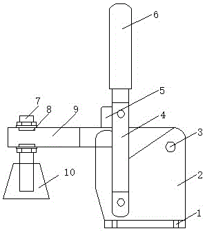
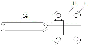
[0017] see Figure 1-3 , the present invention provides a technical solution: a new type of quick clamp, including a right-angle flange 2, a U-shaped handle 4, a horizontal pressure handle 9, a base 11 and a buffer mechanism 13, and the four corners of the base 11 are provided with circular mounting holes 1. Install the base 11 on the machining equipment through the installation hole 1 to quickly clamp the workpiece. The base 11 is provided with a right-angle ...


PUM


Abstract

The invention discloses a novel rapid fixture. The novel rapid fixture comprises a right-angle flange, a U-shaped handle, a horizontal press handle, a base and a buffer mechanism, wherein round mounting holes are formed in four corners of the base, and the right-angle flange is arranged on the base and fixedly welded with the base; a clamping groove is formed in the U-shaped handle which is mounted on the right-angle flange through the clamping groove, the U-shaped handle is in riveting joint with the right-angle flange through a rivet, and the U-shaped handle is fixedly wrapped with a glove; a guide groove is formed in the horizontal press handle which is arranged on the right-angle flange, and the horizontal press handle in riveting joint with the right-angle flange through the rivet; a fixing clamp is arranged in the guide groove of the horizontal press handle, a stud is arranged on the fixing clamp, and a press disc is arranged at the bottom end of the stud. The novel rapid fixture is simple in structure and good in stability, the maximum pressing strength can reach 550 KG, and machining errors caused by workpiece shake in a machining process can be avoided.

Description

technical field [0001] The invention relates to the technical field of application of mechanical clamping devices, in particular to a novel quick clamp. Background technique [0002] In mechanical processing, it is usually necessary to clamp the workpiece with a fixture. The fixture operation on the market is relatively cumbersome, which affects production efficiency. In addition, the workpiece is easy to loose due to the reduction of the clamping force during the processing process, causing the workpiece to fall from the fixture. fall, causing economic losses and even safety hazards; when people spray, dip, corrode, spray (shot) blast and other surface treatment processes on the surface of rod workpieces, they must first spend a lot of manpower and material resources to isolate and protect the surface of the workpiece. The part that needs to be processed is a waste of time and money, and is inefficient; the tightening fixture relies on rotating and tightening electric tools...

Claims


Application Information

Patent Timeline
Patent Type & Authority Applications(China)
IPC IPC(8): B23Q3/00
CPCB23Q3/00
Inventor 沈明涛
Owner WUXI CITY DAWN HIGH STRENGTH FASTENERS
Learn More