Linked punching-shearing system

A linkage, punching machine technology, applied in welding equipment, laser welding equipment, metal processing equipment, etc., can solve the problems of low degree of automation, inconvenient use of punching equipment, low efficiency, etc., to achieve durable service life, economical equipment and maintenance costs

Active Publication Date: 2016-10-26
苏州锐士达工业自动化有限公司
View PDF8 Cites 3 Cited by
  • Summary
  • Abstract
  • Description
  • Claims
  • Application Information

AI Technical Summary

Problems solved by technology

[0012] The purpose of the present invention is to provide a linkage punching system to solve the problems of low degree of automation, inconvenient use of the original punching equipment, and low efficiency

Method used


Image

  • Linked punching-shearing system
  • Linked punching-shearing system
  • Linked punching-shearing system

Examples


Embodiment Construction

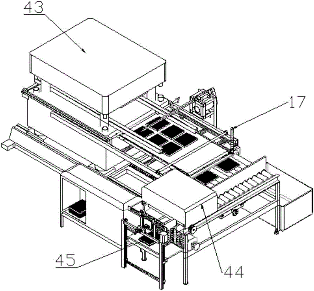
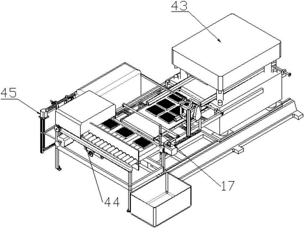
[0042] Such as figure 1 with 2 As shown, a linked punching system includes a punching machine system 43 , a dust removal system 44 and a receiving system 45 .

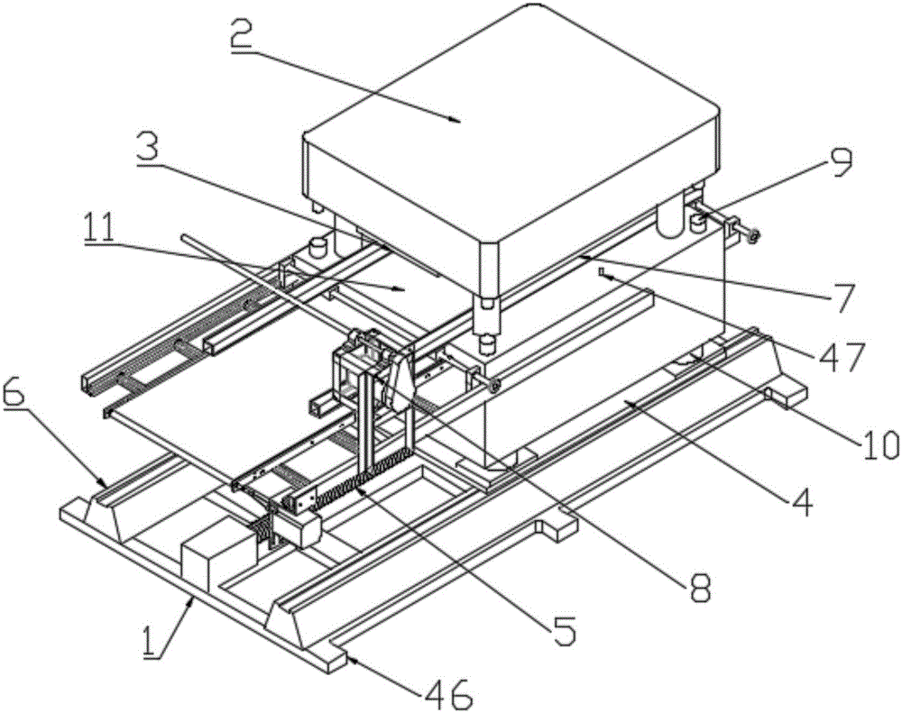
[0043] Such as image 3 with 4 As shown, the punching machine system includes a base 1, horizontal guide rails 6 are provided on both sides of the base 1, and a servo motor is provided at one end of the base 1, and the servo motor is connected to a pressure plate through a sliding screw rod 5 4. Both sides of the pressure bearing plate 4 are located on the horizontal guide rails 6 on both sides of the base 1, so that the pressure bearing plate 4 can slide on the horizontal guide rails 6, and a hydraulic punching machine 2 is correspondingly installed on the horizontal guide rails 6 Above the pressure bearing plate 4, a die structure 3 is provided below the upper hydraulic plate of the hydraulic punching machine 2, and the die structure 3 includes a die absorption plate, and a laser cutting knife is adsorbed on the die...


PUM


Abstract

The invention discloses a linked punching-shearing system which comprises a punching-shearing machine system, a dust removal system and a material collecting system. Efficient and flexible work is realized in a manner that the punching-shearing machine system, the dust removal system and the material collecting system are cooperated.

Description

technical field [0001] The invention belongs to the technical field of plastic forming equipment, and in particular relates to a linkage punching system. Background technique [0002] At present, there are two forms of product blanking in the blister industry: [0003] 1. Segmental blanking (mainstream implementation form): The blister products are cut out by the blister forming machine in a single sheet / full format, and then manually cut into individual products by hydraulic punching machines and other machinery, which wastes work Time affects work efficiency, and the disadvantages are also obvious, such as: [0004] ① Completely rely on manual blanking, resulting in low production efficiency; [0005] ② Production safety issues, unsafe factors for workers operating cutting punches; [0006] ③Product quality problems, there are factors affecting the quality of products in the process of handling and cutting. [0007] 2. Blister online integrated punching (non-mainstream...

Claims


Application Information

Patent Timeline
Patent Type & Authority Applications(China)
IPC IPC(8): B23K26/38B23K26/70
CPCB23K26/38B23K26/702
Inventor 王光辉
Owner 苏州锐士达工业自动化有限公司
Why Eureka
Try Eureka