
Lubricant injector

A lubricating oil and injector technology, which is applied in the direction of lubricating oil control valves, lubricating pumps, lubricating parts, etc., can solve problems such as interruption of injection ports, reduced fluidity of lubricating grease, and inability to inject smoothly, so as to overcome the flow of lubricating oil The difference in quantity, the effect of reducing oil separation degree and saving manufacturing cost

Inactive Publication Date: 2016-10-12
KLT CO LTD
View PDF6 Cites 6 Cited by
  • Summary
  • Abstract
  • Description
  • Claims
  • Application Information

AI Technical Summary

Problems solved by technology

Although this method has the advantage of being able to obtain a higher discharge pressure, in order for the grease to be smoothly injected from the upper part into the pump inlet, it is necessary to use a spring to continuously squeeze the grease, so at a certain moment it will be like In the gas type, the base oil separation phenomenon generally occurs, and the occurrence of the base oil separation phenomenon will reduce the fluidity of the grease and thus cannot be smoothly injected into the pump, and eventually the discharge will be interrupted due to the clogging of the injection port.

Method used


Image

  • Lubricant injector
  • Lubricant injector
  • Lubricant injector

Examples


Embodiment Construction

[0031] Next, a first embodiment to which the present invention is applied will be described in detail with reference to the drawings.

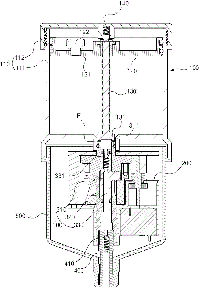
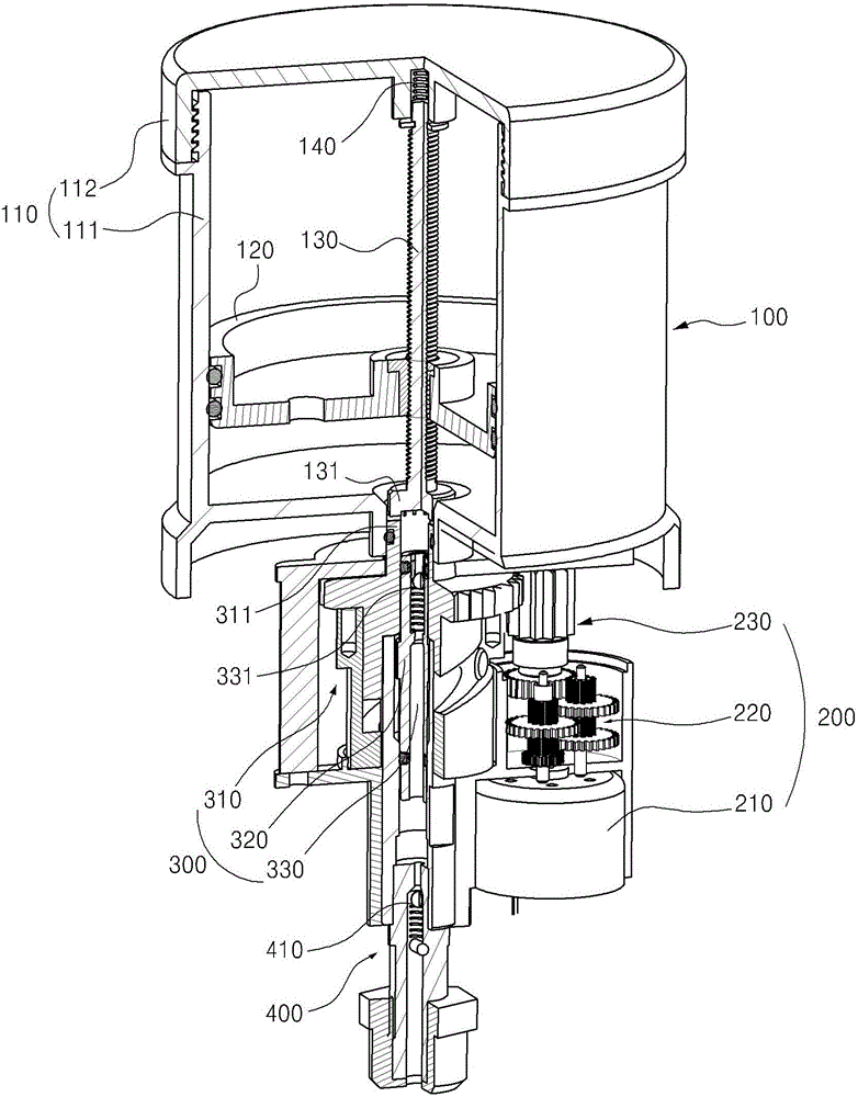
[0032] figure 1 and figure 2 They are respectively a sectional view and a perspective view showing a lubricating oil injector applicable to the first embodiment of the present invention. As shown in the figure, the present invention includes a storage part 100 , a power generation part 200 and a discharge part 300 .

[0033] First, the above-mentioned storage part 100 is filled with lubricating oil that needs to be used at the position where mechanical friction occurs, so as to press the lubricating oil into the discharge part 300, including: storage chamber 110, piston 120, screw shaft 130, driven gear 131 and the elastic support member 140.

[0034] The storage chamber 100 is used to provide a space for filling and storing lubricating oil, and includes: a main body 111 and an outer cover 112 . The main body 111 provides a space for filli...


PUM


Abstract

The purpose of the present invention is to provide a lubricant injector, which implements extrusion and pumping of a lubricant using a single power source, and which can intermittently perform extrusion of the lubricant, the lubricant injector comprising: a storage unit comprising a storage chamber filled with a lubricant, a piston provided inside the storage chamber, a screw shaft coupled to the piston so as to lift / lower the piston according to rotation, a following gear installed on the bottom portion of the screw shaft, and an elastic support member installed on one side of the screw shaft to elastically support the following gear; a power generation unit installed on one side of the lower portion of the storage unit to provide a rotation driving force; and an emission unit comprising a cylindrical cam which interworks with the power generation unit and thereby rotates, a driving gear which is formed on the top portion of the cylindrical cam and meshes with the following gear, thereby forming a space such that the lubricant is introduced into the cylindrical cam, a plunger which interworks with rotation of the cylindrical cam and moves up / down inside the cylindrical cam, thereby pumping the introduced lubricant, and an emission tube line formed inside the plunger such that the pumped lubricant can be emitted to target locations, wherein the following gear and the driving gear intermittently mesh with each other according to the change of pressure inside the storage chamber.

Description

technical field [0001] The invention relates to a lubricating oil injector (LUBRICANT INJECTOR), in particular to a lubricating oil injector which realizes automatic lubricating oil injection by being installed at a position requiring lubrication due to mechanical friction. Background technique [0002] At present, lubricating oil injectors used in places where mechanical friction occurs in general industrial machinery have been widely used, and are widely used in many industries. Although the proportion of lubricating oil injectors in production activities is getting higher and higher, various problems often occur in the process of using lubricating oil injectors due to the following reasons in the actual industrial site. [0003] First of all, the lubricating oil injector is a device used to inject grease, and the structure of grease is based on the physical properties of thickener, base oil (oil) and additive. Binding rather than chemical bonding. That is, the thickener...

Claims


Application Information

Patent Timeline
Patent Type & Authority Applications(China)
IPC IPC(8): F16N31/02F16N13/10
CPCF16N11/08F16N13/14F16N23/00F16N2013/063F16N13/10F16N31/02G01F11/06
Inventor 梁允宗
Owner KLT CO LTD
Learn More