Rolling bearing removal device

A technology of rolling bearings and power devices, which is applied in the direction of electromechanical devices, electric components, and manufacturing motor generators. It can solve the problems of damaged bearing inner rings, low bearing integrity, and low efficiency of bearing removal, and achieve integrity improvement and force application. Average, high-integrity results

Active Publication Date: 2019-03-01
HENAN KAIBANG MOTOR
View PDF5 Cites 0 Cited by
  • Summary
  • Abstract
  • Description
  • Claims
  • Application Information

AI Technical Summary

Problems solved by technology

The defect of this device is: only one rolling bearing 210 on the rotor 200 can be disassembled at a time, and the bearing removal efficiency is low; when an external force is applied to the rolling bearing 210, the inner ring of the bearing is often damaged, resulting in low integrity of the bearing after disassembly

Method used


Image

  • Rolling bearing removal device
  • Rolling bearing removal device
  • Rolling bearing removal device

Examples


Embodiment Construction

[0024] The technical solutions of the present invention will be further described below in conjunction with the accompanying drawings and through specific implementation methods.

[0025] Preferred embodiment:

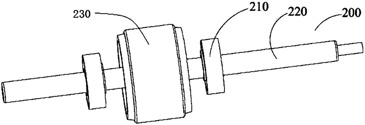
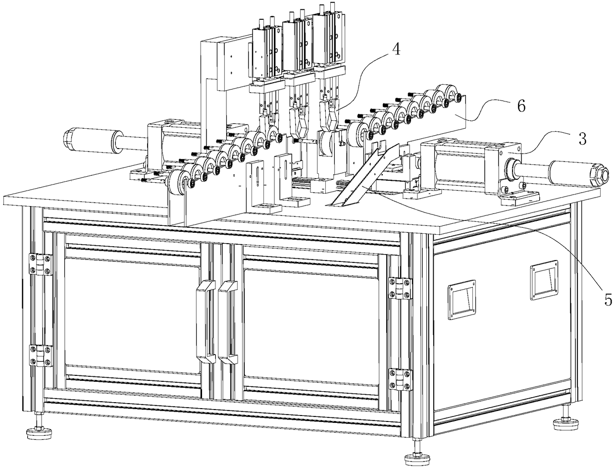
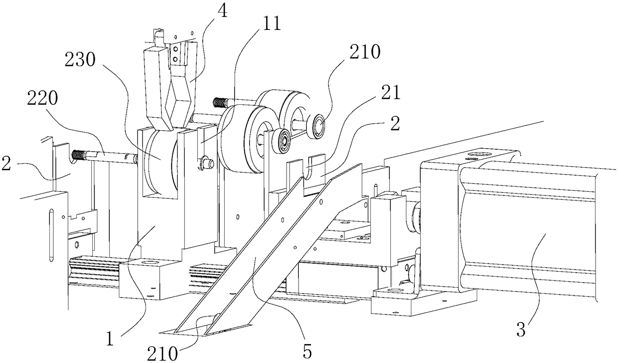
[0026] The preferred embodiment discloses a rolling bearing removal device. Such as Figure 2 to Figure 5 As shown, the rolling bearing removal device includes a U-shaped fixing frame 1 for fixing the rotor main body 230, and two opposite side walls of the U-shaped fixing frame 1 are respectively provided with rotating shaft openings 11 for passing through the rotating shaft 220; Each side of the U-shaped fixed frame 1 is respectively provided with a retracting bearing bracket 2, and the retracted bearing bracket 2 is provided with a bracket opening 21 for passing through the rotating shaft 220, and the U-shaped fixed frame 1 can move between the two retracted bearing brackets 2 ; The force direction of the power unit 3 is the same as the direction of the connecting ...


PUM


Abstract

The invention discloses a rolling bearing dismounting device, belonging to the technical field of a dismantling device and designed to solve the problems seen in existing dismounting devices such as low dismounting efficiency and the easy damage to the inner ring of a rolling bearing. The rolling bearing dismounting device of the present invention comprises a U-shaped fixing frame for fixing a rotor main body and two opposite side walls of the U-shaped fixing frame are each provided with a rotary shaft opening through which a rotary shaft penetrates. Each side of the U-shaped fixing frame is provided with a bearing dismounting support; the bearing dismounting supports are provided with support openings to allow rotary shafts to penetrate. The U-shaped fixing frame is capable of moving between the two bearing dismounting support. The force direction of the power unit is the same as the connection direction between the rotary shaft openings and the support openings. The rolling bearing dismounting device of the invention has high dismounting efficiency without having to adjust the placing way of a rotor to be dismounted. When the rolling bearing is being dismounted, the force exerted thereto becomes more even so as to ensure that after the dismounting process, the inner ring of a rolling bearing does not get damaged, thus ensuring the high integrity of the rolling bearing.

Description

technical field [0001] The invention relates to the technical field of dismantling devices, in particular to a rolling bearing dismantling device. Background technique [0002] The rotor is an integral part of the motor, such as figure 1 As shown, the rotor 200 includes a rotating shaft 220 , on which a rotor main body 230 and two rolling bearings 210 pass through, and the rotor main body 230 is located between the two bearings 210 . Usually, the rolling bearing 210 and the rotating shaft 220 are interference fit. When the rolling bearing 210 and the rotating shaft 220 need to be separated (that is, the bearing is withdrawn), a large external force needs to be applied to the rolling bearing 210 or the rotating shaft 220 . [0003] The existing bearing removal device uses a U-shaped support to clamp a rolling bearing 210 , and then knocks the end of the rotating shaft 220 to separate the rolling bearing 210 from the rotating shaft 220 . The defect of this device is: only on...

Claims


Application Information

Patent Timeline
IPC IPC(8): H02K15/14
CPCH02K15/14
Inventor 王洁王彬侯克锋张永涛彭文伟
Owner HENAN KAIBANG MOTOR
Why Eureka
Try Eureka