Total-reflection display device and driving method thereof

A technology of a display device and a driving method, which can be applied to static indicators, nonlinear optics, instruments, etc., can solve the problems of inability to reflect light, and the limited reflectivity of total reflection display devices.

Active Publication Date: 2016-10-12
BOE TECH GRP CO LTD
View PDF6 Cites 8 Cited by
  • Summary
  • Abstract
  • Description
  • Claims
  • Application Information

AI Technical Summary

Problems solved by technology

[0003] In the existing total reflection display device, refer to figure 1 and figure 2 As shown, the external light is only reflected by the metal layer 2 (for example: common electrode or pixel electrode, etc.) located in the display area of ​​the array substrate 1; etc.) are generally made of metal materials and also have light reflection ability, but they are blocked by the black matrix 7 (Black Matrix, BM) on the color filter substrate 6 and cannot reflect light, resulting in the limited reflection ability of the above-mentioned total reflection display device

Method used


Image

  • Total-reflection display device and driving method thereof
  • Total-reflection display device and driving method thereof
  • Total-reflection display device and driving method thereof

Examples


Embodiment 1

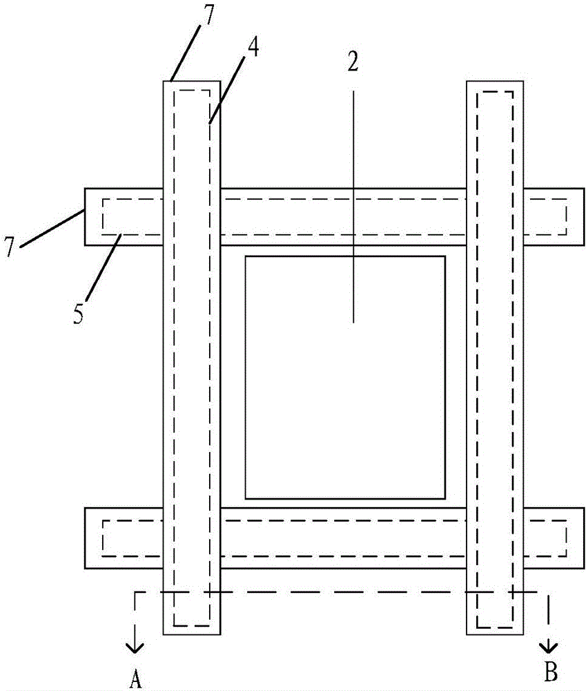
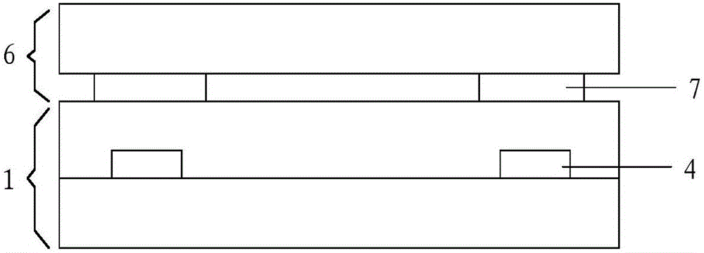
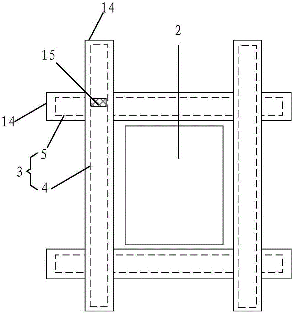
[0041] An embodiment of the present invention provides a total reflection display device. A signal line is provided in the display area of ​​the total reflection display device, and the signal line is made of a metal material; the total reflection display device further includes: a transparency adjustment member; The part is far away from the display surface of the total reflection display device, and along the thickness direction of the total reflection display device, the transparency adjustment part overlaps with the signal line; the transparency adjustment part is used to control the external light from irradiating the signal line by adjusting its own transparency The intensity of the light in the portion of the frame that overlaps the transparency modifier.

[0042] The overlapping portion of the transparency adjusting member and the signal line includes two meanings: first, the transparency adjusting member completely overlaps the signal line; second, the transparency adj...

Embodiment 2

[0069] An embodiment of the present invention provides a method for driving a total reflection display device. The transparency adjustment member of the total reflection display device may be the electrotransparency adjustment member provided in Embodiment 1. The driving method includes:

[0070] During the display period, brightness information of external light is detected. The luminance information here can be parameters such as light intensity, luminous flux, and illuminance, and only one of the parameters needs to be obtained in practical applications.

[0071]When the brightness information indicates that the brightness of the external light is greater than the threshold value, input the first control signal to the transparency adjusting part, so that the transparency adjusting part exhibits the first transparency; when the brightness information indicates that the brightness of the external light is less than the threshold value, input the first control signal to the tra...


PUM


Abstract

The invention provides a total-reflection display device and a driving method thereof. The total-reflection display device is used for improving the problem of limited reflecting capability caused by blockage of signal lines by black matrixes. The signal lines are arranged inside a display zone of the total-reflection display device; the signal lines are made of a metal material; the total-reflection display device further comprises a transparence regulating component; the signal lines are away from the display surface of the total-reflection display device relative to the transparence regulating component, and in the thickness direction of the total-reflection display device, the transparence regulating component and the signal lines have an overlapped part; and the transparence regulating component is used for controlling the light intensity of external light irradiating onto the overlapped part of the signal lines and the transparence regulating component by regulating the self transparence. The invention is applicable to manufacturing of the total-reflection display device.

Description

technical field [0001] The invention relates to the field of display technology, in particular to a total reflection display device and a driving method thereof. Background technique [0002] A total reflection display device, as a new type of display device that has appeared in recent years, has attracted people's attention. It realizes display by reflecting external light without setting a backlight on the back, thereby greatly reducing power consumption of the display. [0003] In the existing total reflection display device, refer to figure 1 and figure 2 As shown, the external light is only reflected by the metal layer 2 (for example: common electrode or pixel electrode, etc.) located in the display area of ​​the array substrate 1; etc.) are generally made of metal materials and also have reflective ability, but are blocked by the black matrix 7 (Black Matrix, BM) on the color filter substrate 6 and cannot reflect light, resulting in limited reflective ability of the...

Claims


Application Information

Patent Timeline
Patent Type & Authority Applications(China)
IPC IPC(8): G02F1/153G02F1/155G02F1/163G09G3/38
CPCG02F1/153G02F1/155G02F1/163G09G3/38
Inventor 刘冬妮陈小川杨盛际肖丽卢鹏程付杰王磊岳晗方正
Owner BOE TECH GRP CO LTD
Why Eureka
Try Eureka