
Radar LFM composite waveform design method

A composite waveform and design method technology, applied in the field of radar communication, can solve problems such as difficulty in obtaining approximate quadratic phase characteristics of LFM waveform, less time-consuming, limited initial solution setting, etc.

Active Publication Date: 2016-10-12
HARBIN INST OF TECH AT WEIHAI
View PDF6 Cites 18 Cited by
  • Summary
  • Abstract
  • Description
  • Claims
  • Application Information

AI Technical Summary

Problems solved by technology

However, this kind of CAN algorithm converges slowly for constant modulus non-convex problems, takes too long and is limited by the initial solution setting, which is difficult to meet engineering needs
The improved cycle algorithm based on alternate projections has achieved more obvious results than the CAN algorithm (see literature: Computational design of optimal waveforms for MIMO radarvia multi-dimensional iterative spectral approximation, Zhao Y N, Li F C, ZhangT; Multidmsyst sign process, 11045- 01400288-1, 2014), but the alternating projection algorithm also has local stagnation for solving the convex norm and is difficult to converge (see literature: An alternating projection that does notconverge in norm, Hundal H S, Nonlinear Analysis: Theory, Methods & Applications, 2004, 57( 1):35-61), and the relaxed projection algorithm as an efficient and less time-consuming algorithm can obtain a stable consistent global solution (see literature: Relaxed alternating projection methods, A.Cegielski, A.Suchocka, SIAM Journal on Optimization, vol.19(3), 2008, pp.1093-1106), but this algorithm is difficult to obtain the approximate quadratic phase characteristics of the LFM waveform under the condition of ensuring the amplitude constraint of the LFM noise waveform

Method used


Image

  • Radar LFM composite waveform design method
  • Radar LFM composite waveform design method
  • Radar LFM composite waveform design method

Examples


Embodiment

[0049] The present invention proposes a kind of radar LFM composite waveform design method, which comprises the following steps:

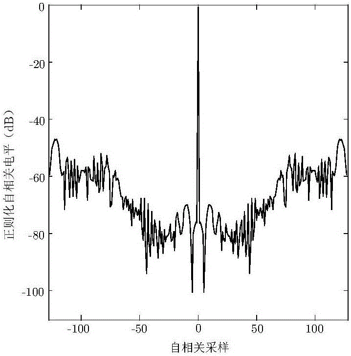
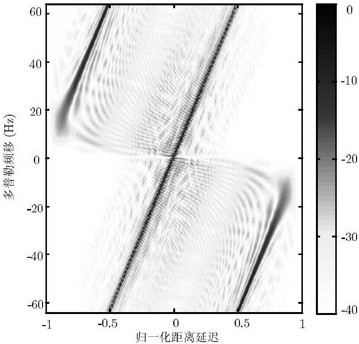
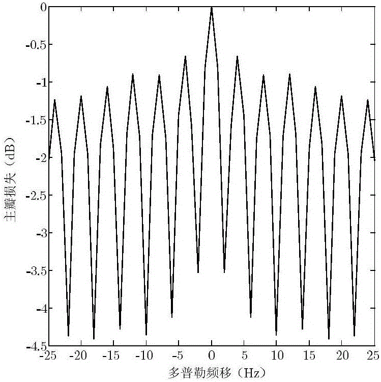
[0050] Step 1: Construct the LFM composite waveform signal model. In order to ensure that the transmitter works in a saturated state, it is assumed that the discrete baseband constant-mode LFM waveform with a code length of N can be expressed as: s=[s(1) s(2) ... s (N)] T , where, s(n)=exp(jπμ·(n-1) 2 ), n∈{1,...,N}, μ is the frequency modulation slope of the LFM waveform, and exp(·) represents an exponential function; in addition, it is assumed that the constant modulus random phase waveform can be expressed as: p=[p(1) p (2) ... p(N)] T , where p(n)=exp(jρ n ), phase ρ n Obey the uniform distribution of [-π, π]; the construction of LFM composite waveform is composed of LFM waveform and random phase waveform. The LFM composite waveform can be regarded as the deterministic quadratic phase of the LFM waveform and the random phase of the random p...


PUM


Abstract

The invention belongs to the radar communication technology field and particularly relates to a radar LFM composite waveform design method which has properties of Doppler tolerance, low interception probability characteristic and low relevant sidelobe characteristic and is for motion target information acquisition. The radar LFM composite waveform design method is in combination with a low relevant sidelobe waveform design method and an LFM noise waveform design concept, an LFM composite waveform mathematics model is constructed in a phase weight mode, and relevant sidelobe template vectors are introduced to construct a corresponding target function; phase constraint and constant modulus constraint conditions are analyzed, an iteration spectral approximation relaxed projection phase correction algorithm framework is constructed, LFM composite waveform optimization output programmed steps are provided, iteration spectral approximation relaxed projection phase correction constant modulus LFM composite waveform coding design concepts as described are employed, and the low relevant sidelobe characteristic and the low interception probability characteristic of waveforms can be relatively improved. The method further has properties of high efficiency, small time consumption and good robustness, and the method is more suitable for LFM composite waveform online design.

Description

technical field [0001] The invention belongs to the technical field of radar communication, in particular to a radar LFM composite waveform design method for moving target information acquisition with Doppler tolerance and low correlation side lobe characteristics. Background technique [0002] Radar scenarios are becoming increasingly complex, and radar systems with low intercept probability and low identification probability characteristics have become important tactical requirements. Among them, waveform design can be regarded as an effective way to achieve this requirement. [0003] The Linear Frequency Modulation (LFM) waveform has a "slanted knife-edge" ambiguity function and better Doppler tolerance, but its autocorrelation sidelobe is high and the waveform is easy to be intercepted. The random phase waveform has an ideal "thumbtack" ambiguity function, which can obtain high range-Doppler resolution and the phase information is not easy to be intercepted, but its poor...

Claims


Application Information

Patent Timeline
IPC IPC(8): G01S7/02G06F17/50
CPCG01S7/02G06F30/367
Inventor 赵宜楠冯翔潘恒康赵占锋周志权
Owner HARBIN INST OF TECH AT WEIHAI
Learn More