
Method for monitoring and positioning crack development areas in coal and rock fracture procedures by means of infrared radiation

A technology of infrared radiation and positioning method, which is applied in the direction of applying stable tension/pressure to test the strength of materials, measuring devices, instruments, etc. Accumulated heat and other problems to achieve the effect of eliminating the cumulative heat (thermo-mechanical coupling) effect, effectively extracting, and improving the saliency and accuracy

Inactive Publication Date: 2016-10-12
CHINA UNIV OF MINING & TECH
View PDF5 Cites 19 Cited by
  • Summary
  • Abstract
  • Description
  • Claims
  • Application Information

AI Technical Summary

Problems solved by technology

At present, scholars at home and abroad have done a lot of research on the infrared radiation characteristics of the coal rock fracture and instability process, but there are the following problems: (1) when judging whether the coal rock is in a micro-cracked or damaged state, the average infrared radiation temperature (AIRT), The maximum (minimum) value and other indicators, and these indicators are not easy to be observed and changed during the actual test of the coal rock sample bearing fracture, so it is impossible to quickly and effectively capture the exact moment of coal rock fracture instability; (2) only use When the index of the original infrared thermal image sequence map is used to judge the crack development area in the process of bearing coal-rock fracture, the cumulative heat (thermomechanical coupling) effect in the process of bearing-bearing coal-rock fracture is ignored, and it cannot be significantly and accurately judged. Infrared Radiation Abnormal Information

Method used


Image

  • Method for monitoring and positioning crack development areas in coal and rock fracture procedures by means of infrared radiation
  • Method for monitoring and positioning crack development areas in coal and rock fracture procedures by means of infrared radiation
  • Method for monitoring and positioning crack development areas in coal and rock fracture procedures by means of infrared radiation

Examples


Embodiment Construction

[0026] The present invention will be further described below in conjunction with the accompanying drawings and specific embodiments, so that those skilled in the art can understand the present invention.

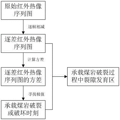
[0027] like figure 1 Shown is a flow chart of the present invention, the infrared radiation monitoring and positioning method of the fracture development zone in the coal rock fracture process, comprising the following steps:

[0028] a. Obtain the original infrared radiation information in the process of bearing coal rock fracture. Before implementing this step, it is necessary to prepare the infrared radiation detection system in advance, such as figure 2 shown. The infrared radiation detection system includes a press 1, a plastic film 2, a bearing coal rock 3, an isolated closed box 4, an infrared thermal imager 5 and a data acquisition instrument 6; a press 1, a plastic film 2, a bearing coal rock 3 and an infrared thermal The imagers 5 are all located inside the iso...


PUM


Abstract

The invention provides a method for monitoring and positioning crack development areas in coal and rock fracture procedures by means of infrared radiation, and relates to the field of water conservation mining and rock stratum control. The method is applicable to detecting crack development laws and development locations in coal and rock fracture research procedures. The method includes determining bearing coal and rock fracture and failure time nodes by the aid of variance indexes of successive difference infrared thermal imaging sequence diagrams; extracting infrared thermal imaging diagrams at current moments according to the time nodes on the basis of the time nodes to position the crack development areas at bearing coal and rock fracture moments so as to temporally and spatially predict the crack development areas. The method has the advantages that research results can be applied to monitoring and controlling human engineering disasters such as coal (rock) burst and mine water inrush due to bearing coal and rock fracture, and the method particularly has scientific significance on enriching water conservation mining and rock stratum control theories for mines.

Description

technical field [0001] The invention relates to the field of water conservation mining and rock formation control, in particular to an infrared radiation monitoring and positioning method for a crack development area in the coal rock rupture process. Background technique [0002] The fracture instability of coal and rock is the root cause of coal (rock) explosion, mine pillar yield collapse, mine water inrush and mine earthquake and other mine disasters. Studies have shown that in the process of bearing stress, deformation and fracture of coal rock, the intensity of electromagnetic radiation including infrared bands will change with the change of stress, and thermal infrared anomalies will appear when the fracture is unstable. Correctly understanding the infrared radiation characteristics in the process of coal fracture instability, finding out the crack development law in the process of coal fracture, and then accurately and effectively monitoring the coal fracture process ...

Claims


Application Information

Patent Timeline
IPC IPC(8): G01N3/08G01N3/06
CPCG01N3/08G01N3/068G01N2203/0019G01N2203/0647
Inventor 马立强张东升周焘孙海
Owner CHINA UNIV OF MINING & TECH
Learn More