Electric motor starter with function of manual turning

A kind of starter and electric technology, applied in the direction of starting device with mechanical power storage, motor starting for engine, starting device with manual crank, etc., it can solve the problems of low efficiency, potential safety hazards, casualties and other problems, and achieve accurate The effect of positioning, improving efficiency, and eliminating potential safety hazards

Active Publication Date: 2016-10-12
CHONGQING STARTING POWER UNIT CO LTD
View PDF5 Cites 6 Cited by
  • Summary
  • Abstract
  • Description
  • Claims
  • Application Information

AI Technical Summary

Problems solved by technology

During engine inspection and maintenance, only the steel crowbar can be used to pry the engine flywheel ring gear to rotate. Although it can realize slow and accurate rotation, there are potential safety hazards (such as the operator forgets to remove the steel crowbar, and when the engine flywheel ring gear rotates Causing casualties or equipment failure by ejecting the steel crowbar), low efficiency

Method used


Image

  • Electric motor starter with function of manual turning
  • Electric motor starter with function of manual turning
  • Electric motor starter with function of manual turning

Examples


Embodiment 1

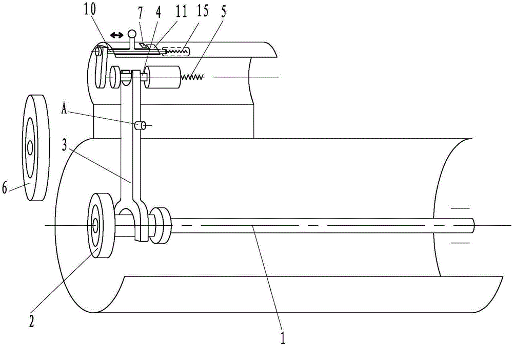
[0028] Such as figure 2 As shown, the shifting gear mechanism is composed of a push rod mechanism 10 , a normally closed switch 7 , a locking groove 11 and a second return spring 15 . The push rod mechanism 10 is used as a force-bearing member, the locking groove 11 is used as a positioning member, and the second return spring 15 is used as a first return member. The push rod mechanism 10 is located directly above the electromagnetic relay guide rod 4. The top of the push rod mechanism 10 has a toggle handle. The left end of the push rod mechanism 10 extends downward to form a push plate facing the electromagnetic relay guide rod 4, and the locking groove 3 on the electric starter housing, the second return spring 15 is installed on the right end of the push rod mechanism 10, and the electric starter housing is also provided with a chute for the toggle handle on the top of the push rod mechanism 10 to pass through.

[0029] The handle is moved by external force, and the push...

Embodiment 2

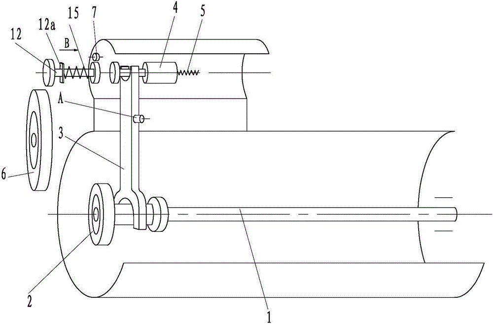
[0031] Such as image 3 , Figure 4 As shown, the gear shifting mechanism is composed of a push rod 12 , a normally closed switch 7 and a second return spring 15 . The push rod 12 is used as a force-bearing member. The locking clip 12a provided on the push rod 12 and the corresponding notch 16 on the electric starter housing form a positioning member, and the second return spring 15 serves as a first return member. The push rod 12 is located on the left side of the electromagnetic relay guide rod 4, the push rod 12 is provided with a locking clip 12a, the left end of the push rod 12 is provided with a pressing plate, the right end of the push rod 12 is provided with a push plate, and the electric starter shell is provided with a Facing the notch 16 of the locking clip 12a, the second return spring 15 is sleeved on the push rod 12 .

[0032]The external force presses the plate, and the push plate pushes the guide rod 4 of the electromagnetic relay to move to the right. When t...

Embodiment 3

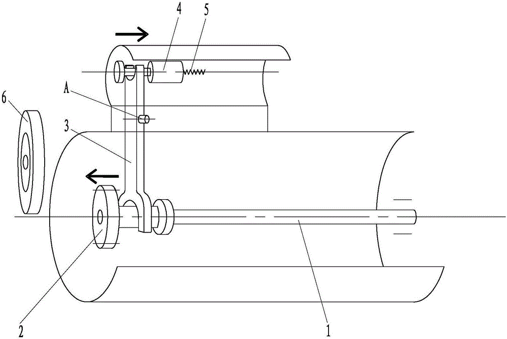
[0034] Such as Figure 5 As shown, the shifting gear mechanism is composed of a clamping plate 14, a normally closed switch 7 and a shifting fork extension rod 13 formed by extending the top end of the shifting fork 3 upwards. The electric starter housing is provided with a chute for the toggle handle at the top of the shift fork extension rod 13 to pass through.

[0035] External force acts on the toggle handle at the top of the shift fork extension rod 13, and the toggle handle stretches out of the electric starter housing. The electromagnetic relay guide rod 4 is pushed to the right by the shift fork extension rod 13. When the shift fork extension rod 13 moves to the limit position, the shift fork extension rod 13 is locked after the clamp plate 14 is rotated, and the normally closed switch 7 cuts off the electric starter. The power supply makes the driving gear mechanism 2 mesh with the engine flywheel ring gear 6, and the shift fork extension rod 13 automatically returns...


PUM


Abstract

The invention discloses an electric motor starter with the function of manual turning. A main shaft, a drive gear mechanism, a shifting fork, an electromagnetic relay guide rod and a first return spring are arranged in a shell of the electric motor starter. A gear shifting mechanism comprises a force exertion piece, a normally-closed switch, a locating piece and a first return piece. The force exertion piece extends out of the shell of the electric motor starter to serve as an external force application point and drives the electromagnetic relay guide rod to move rightwards. The normally-closed switch is used for cutting off a power source of the electric motor starter when the force exertion piece moves to the limiting position. The locating piece is used for locking the force exertion piece when the force exertion piece moves to the limiting position. The first return piece is used for automatic return after the force exertion piece is unlocked. Two manners that the transmission mechanism is used for indirect turning for main shaft rotation and a turning tool is used for direct turning for main shaft rotation are adopted in a turning mechanism. On the premise of not influencing the existing function of a traditional electric motor starter, the structure of the electric motor starter is improved, the function of manual turning is added, an engine flywheel gear ring can be accurately located during maintenance, efficiency is improved, and potential safety hazards are eliminated.

Description

technical field [0001] The invention relates to an electric starter used for engine inspection and maintenance, which adds a manual cranking function to the existing electric starter, and belongs to the technical field of mechanical structures. Background technique [0002] The vast majority of modern engines are equipped with electric starters, such as figure 1 As shown, the housing of the electric starter is provided with a main shaft 1 , a drive gear mechanism 2 , a shift fork 3 , an electromagnetic relay guide rod 4 and a first return spring 5 . The guide rod 4 of the electromagnetic relay moves to the right, and pushes the shift fork 3 to rotate clockwise around the hinge point A, the upper end of the shift fork 3 compresses the first return spring 5, and the lower end of the shift fork 3 pushes the main shaft 1 to move to the left, so that the drive gear The mechanism 2 meshes with the flywheel ring gear 6 of the engine, and the flywheel ring gear 6 is driven by the m...

Claims


Application Information

Patent Timeline
Patent Type & Authority Applications(China)
IPC IPC(8): F02N11/10F02B77/00
CPCF02B77/00F02N11/101F02N1/00F02N11/00F02N15/067F02N11/106F02N11/108F02N1/02F02N2250/00F02N1/005F02N11/10F02N11/08F02B77/083F02N11/0851F02N15/062F02N2200/04F16H35/18
Inventor 刘树权林阳光朱达安
Owner CHONGQING STARTING POWER UNIT CO LTD
Why Eureka
Try Eureka