A kind of self-swinging double-wheel roller tank ear

A roller tank ear and double wheel technology is applied in elevators, lifting equipment in mines, transportation and packaging, etc. It can solve the problems of poor buffering effect and rubber wheel wear, etc., to extend service life, reduce wear, and reduce self-weight. Effect

Active Publication Date: 2018-03-02
SHANDONG NUOTAI ELECTRICAL EQUIP CO LTD
View PDF9 Cites 0 Cited by
  • Summary
  • Abstract
  • Description
  • Claims
  • Application Information

AI Technical Summary

Problems solved by technology

[0005] The purpose of the present invention is to provide a self-swinging double-wheel roller can ear, which solves the problems of poor buffering effect of the traditional roller can ear and serious rubber wheel wear

Method used


Image

  • A kind of self-swinging double-wheel roller tank ear
  • A kind of self-swinging double-wheel roller tank ear

Examples


Embodiment Construction

[0014] The present invention will be further described below in conjunction with accompanying drawing.

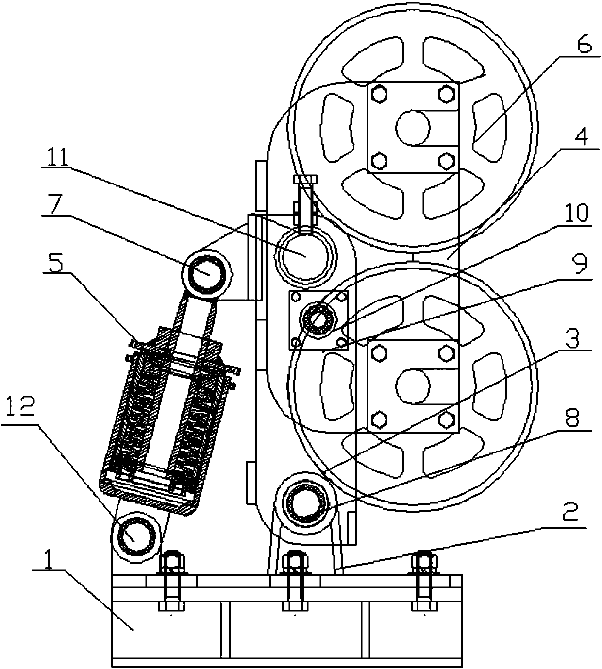
[0015] Such as figure 1 and 2 As shown, the self-swinging double-wheel roller can ear includes a base 1, a lower bracket 2, an upper bracket 3, a swing frame 4, and a disc spring buffer device 5. The lower bracket 2 is fixed on the base 1 by bolts, and the lower bracket 2 is fixed on the base 1 by bolts. A support plate links to each other with the disc spring buffer device 5 and the upper bracket 3 respectively through pin shaft I-b12 and pin shaft II8, and the disc spring buffer device 5 connects the lower bracket 2 and the upper bracket 3 through the pin shaft I-a7, and By adjusting the stroke of the disc spring buffer device 5 to adjust the pre-tightening force between the roller tank ear and the tank channel; the swing frame 4 is connected to the upper bracket 3 through the pin shaft III 11, and the swing frame 4 and the upper bracket 3 are provided with The swing po...


PUM


Abstract

The invention discloses a self-swinging double-wheel hoop directing device. The self-swinging double-wheel hoop directing device comprises a base, a lower support, an upper support, a swinging frame and a disc spring buffering device. The lower support is fixed to the base through bolts. A front supporting plate and a rear supporting plate of the lower support are correspondingly connected with the disc spring buffering device and the upper support through a pin shaft I-b and a pin shaft II. The lower support and the upper support are connected together through a pin shaft I-a by means of the disc spring buffering device. The swinging frame is connected to the upper support through a pin shaft III. A swinging locating device is arranged between the swinging frame and the upper support. The self-swinging double-wheel hoop directing device further comprises polyurethane rolling wheel assemblies. The polyurethane rolling wheel assemblies are mounted on the swinging frame through shaft holes and are each composed of polyurethane rubber wheels, a bearing seat, rubber wheel covers and a rubber wheel shaft. The number of the polyurethane rubber wheels in each polyurethane rolling wheel assembly is two. By the adoption of the self-swinging double-wheel hoop directing device, the problems that by means of a traditional hoop directing device, the buffering effect is poor, and wear to the rubber wheels is serious are solved.

Description

technical field [0001] The invention relates to mining equipment, in particular to a self-swinging double-wheeled roller tank lug, which belongs to the technical field of tank guide devices for vertical shaft hoisting containers. Background technique [0002] Roller tank ear is a tank guide device for vertical shaft lifting container, which is composed of base bracket, swing arm bracket, roller and buffer. It mainly provides guiding device for lifting container in operation, and is widely used in mines, coal and other industrial production technology field. [0003] At present, more and more large and medium-sized mines are using square pipe tanks. Because the quality of rigid tanks widely used in my country is generally poor, it is prone to local protrusions or subsidence, dislocation, bending, and distortion. [0004] Traditional roller tank lugs are equipped with a single roller. When a single roller runs up and down the deformed tank road, it is prone to bumps, local im...

Claims


Application Information

Patent Timeline
Patent Type & Authority Patents(China)
IPC IPC(8): B66B7/02B66B17/04
CPCB66B7/022B66B7/027B66B7/028B66B17/04
Inventor 杨建奎胡刘扣武云强蒋坤张保臣
Owner SHANDONG NUOTAI ELECTRICAL EQUIP CO LTD
Why Eureka
Try Eureka