
Automatic feeding device

The technology of a feeding device and a feeding car is applied in the field of automatic feeding device, which can solve the problems of affecting processing efficiency, poor accuracy of manipulator taking, and displacement of the feeding car, so as to achieve the effects of improving processing efficiency, good positioning, and improving accuracy.

Active Publication Date: 2016-10-12
宁波宫铁智能科技有限公司
View PDF5 Cites 17 Cited by
  • Summary
  • Abstract
  • Description
  • Claims
  • Application Information

AI Technical Summary

Problems solved by technology

[0003] In the existing feeding equipment, the material truck has the following technical problems. 1. Due to the large moving range of the material truck, it is usually unable to move quickly and accurately to the fixed waiting point, resulting in the inability of the manipulator to accurately pick up the material; 2. The material truck After moving to the predetermined pick-up point, it is not in a fixed state, which will easily lead to the displacement of the feeding cart, resulting in poor picking accuracy of the manipulator, so that the pick-up cannot be done normally, which will affect the processing efficiency

Method used


Image

  • Automatic feeding device
  • Automatic feeding device
  • Automatic feeding device

Examples


Embodiment Construction

[0041] The following are specific embodiments of the present invention and in conjunction with the accompanying drawings, the technical solutions of the present invention are further described, but the present invention is not limited to these embodiments.

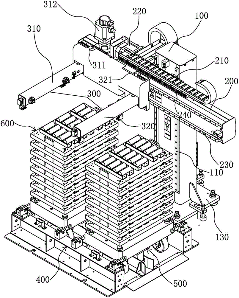
[0042] Such as figure 1 As shown, an automatic feeding device of the present invention includes a vertical arm 100 , a cross arm 200 , a manipulator assembly 300 , a fixed table 400 , a feeding cart 500 and a pallet body 600 .

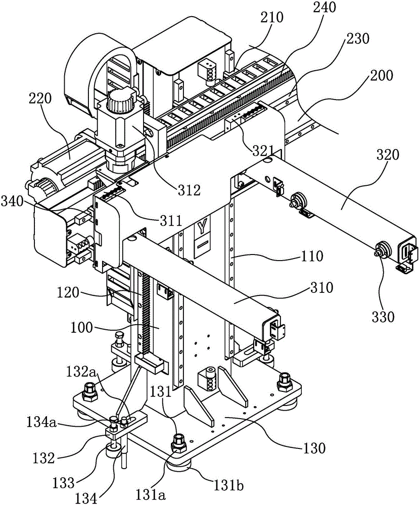
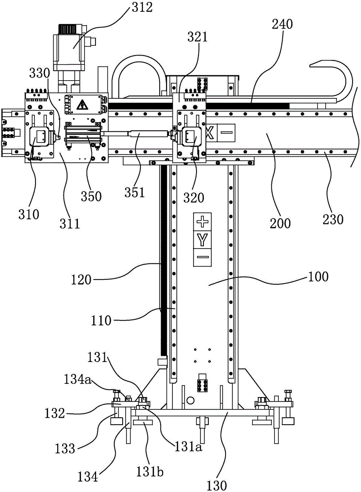
[0043] Such as Figure 1 to Figure 3 As shown, the vertical arm 100 is erected and fixedly connected to a mounting surface. The mounting surface can be the ground or the surface of a certain fixed object. Two first guide rails 110 are erected on the vertical surface of the vertical arm 100. , a first rack 120 is mounted on an outer wall of the vertical arm 100 .

[0044] Such as Figure 1 to Figure 3 As shown, the cross arm 200 is arranged horizontally, and two first sliders 210 are erected on t...


PUM


Abstract

The invention provides an automatic feeding device and belongs to the technical field of automatic machining. By the adoption of the automatic feeding device, the technical problems that a feed trolley in existing feeding equipment cannot be moved to a fixed to-be-taken point rapidly and accurately, and the positioning effect is poor are solved. The automatic feeding device comprises a vertical arm, a cross arm, a manipulator assembly, a fixed stand, a feed trolley and a plurality of tray main bodies, wherein the vertical arm is vertically arranged and fixedly connected with an installation surface; the cross arm is horizontally arranged and movably connected with the vertical arm, and the cross arm can move vertically on the vertical arm; the manipulator assembly is horizontally and movably connected with the cross arm and can move horizontally on the cross arm; the fixed stand is located on one side of the vertical arm and below the manipulator assembly, and the fixed stand is fixedly connected with the installation surface; the feed trolley can move into or out of the fixed stand; and the tray main bodies are arranged on the feed trolley in a stacked mode. Under the positioning and guiding effects of a guide column, the feed trolley can be positioned rapidly and enter the fixed stand so as to be accurately moved to the fixed to-be-taken point, and through main limiting blocks and auxiliary blocks, the feed trolley is limited on the fixed stand and prevented from moving.

Description

technical field [0001] The invention belongs to the technical field of automatic processing and relates to an automatic feeding device. Background technique [0002] In automatic processing equipment, it usually includes feeding equipment. The feeding equipment usually includes a manipulator and a feeding car. The feeding car is stacked with trays for placing rough workpieces. The feeding car transports the rough workpieces to a fixed waiting point, and then passes through The manipulator clamps the rough workpiece and sends it to the processing end for processing. After the rough workpiece is processed into a finished product, it is sent to the material tray of the feeder truck, and finally the feeder truck moves the finished workpiece out of the waiting point. [0003] In the existing feeding equipment, the material truck has the following technical problems. 1. Due to the large moving range of the material truck, it is usually unable to move quickly and accurately to the ...

Claims


Application Information

Patent Timeline
Patent Type & Authority Applications(China)
IPC IPC(8): B65G35/00B65G47/90B65G59/02
CPCB65G35/00B65G47/901B65G59/023B65G2201/0258
Inventor 朱建群
Owner 宁波宫铁智能科技有限公司
Learn More