Deformable flat mop with automatic water squeezing function

A flat mop and horizontal plate technology, applied in the direction of cleaning floors, carpets, cleaning equipment, etc., can solve the problems of inactivity and large space, and achieve the effect of saving space

Active Publication Date: 2016-10-12
林何
View PDF12 Cites 3 Cited by
  • Summary
  • Abstract
  • Description
  • Claims
  • Application Information

AI Technical Summary

Problems solved by technology

[0003] The disadvantages of the existing self-squeezing horizontal mop are that the squeeze head is fixed and cannot be moved, and the squeeze head protrudes horizontally on the mop rod, so it occupies a large space

Method used


Image

  • Deformable flat mop with automatic water squeezing function
  • Deformable flat mop with automatic water squeezing function
  • Deformable flat mop with automatic water squeezing function

Examples


Embodiment 1

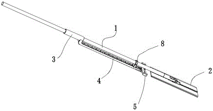
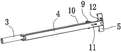
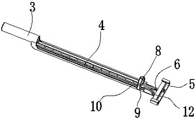
[0031] refer to figure 1 , figure 2 , image 3 , Figure 4 , a deformable self-squeezing horizontal mop, comprising a mop rod 1, a flat mop head 2 movably connected to the lower end of the mop rod 1, and the mop rod 1 is also provided with a squeeze handle that can slide up and down along the mop rod 1 3. The water squeezing handle 3 is connected to the water squeezing head 5 through the connecting rod 4, and the flat mop head 2 can be rotated to be parallel to the mop rod 1 and facing the water squeezing head 5, and the water squeezing handle 3 and The mop rods 1 can slide relative to each other, so that the flat mop head 2 can enter the squeeze head 5 when squeezing water and slide relatively between the two to squeeze water through the squeeze head 5; when mopping the floor The flat mop head 2 breaks away from the squeeze head 5 .

[0032] The water squeezing head 5 is hinged on the lower end of the connecting rod 4 , and the water squeezing head 5 in this embodiment i...

Embodiment 2

[0041]In this embodiment, the mop rod includes an upper rod, a lower rod that is sleeved in the upper rod and can slide axially, and the flat mop head is connected to the lower end of the lower rod; It is fixed on the described upper rod, and the described rack is fixed on the described lower rod. That is to say, in this embodiment, the water squeezing head is fixed, and the lower rod is operated to reciprocate axially back and forth during water squeezing, so that the flat mop head moves back and forth in the water squeezing head to achieve the purpose of water squeezing. The lower rod described in this embodiment is fixed with a positioning protruding ring, the rack is integrated with the positioning protruding ring, the positioning protruding ring is provided with a guide hook, and the connecting rod is An axial slide rail is provided, and the guide hook is hooked on the slide rail to play a guiding role.

[0042] The rest of the structure and implementation are the same a...


PUM


Abstract

A deformable flat mop with an automatic water squeezing function comprises a mop rod and a flat mop head movably connected to the lower end of the mop rod, wherein a water-squeezing handle is further arranged on the mop rod and connected with a water squeezing head through a connecting rod; the flat mop head can rotate to be parallel to the mop rod and face the water squeezing head; the water-squeezing handle and the mop rod can slide relatively; the water-squeezing head is hinged to the lower end of the connecting rod; a switching device is arranged between the mop rod and the water squeezing head, and the water squeezing head rotates and unfold transversely under the action of the switching device during water squeezing, so that the flat mop head can enter the water squeezing head; after water squeezing, the water squeezing head is enabled to rotate to be retracted axially under the action of the switching device. According to the deformable flat mop with the automatic water squeezing function, folding retraction of the water squeezing head can be realized after water squeezing, transverse space is not occupied, and space is greatly saved.

Description

technical field [0001] The invention relates to a self-extruding horizontal mop. Background technique [0002] The existing self-squeezing horizontal mop generally includes a mop rod and a flat mop head movably connected to the lower end of the mop rod. The water head, the flat mop head can be inserted into the squeeze head, when the flat mop head enters the squeeze head, push and pull the squeeze handle back and forth, so that the squeeze head moves back and forth to squeeze water on the wipes on the flat mop head. [0003] The disadvantage of the existing self-squeezing horizontal mop is that the squeeze head is fixed and cannot be moved, and the squeeze head protrudes laterally from the mop rod, thus occupying a relatively large space. Contents of the invention [0004] In order to overcome the above-mentioned shortcomings of the existing self-squeezing horizontal mop, the present invention provides a deformable self-squeezing horizontal mop with a movable squeezin...

Claims


Application Information

Patent Timeline
Patent Type & Authority Applications(China)
IPC IPC(8): A47L13/14A47L13/20
CPCA47L13/14A47L13/258A47L13/20
Inventor 林何
Owner 林何
Why Eureka
Try Eureka