Channel measuring method and device
A channel measurement and quantity technology, applied in the field of communication, can solve the problem of unable to meet the increasing number of base station antenna ports.
- Summary
- Abstract
- Description
- Claims
- Application Information
AI Technical Summary
Problems solved by technology
Method used
Image
Examples
Embodiment 1
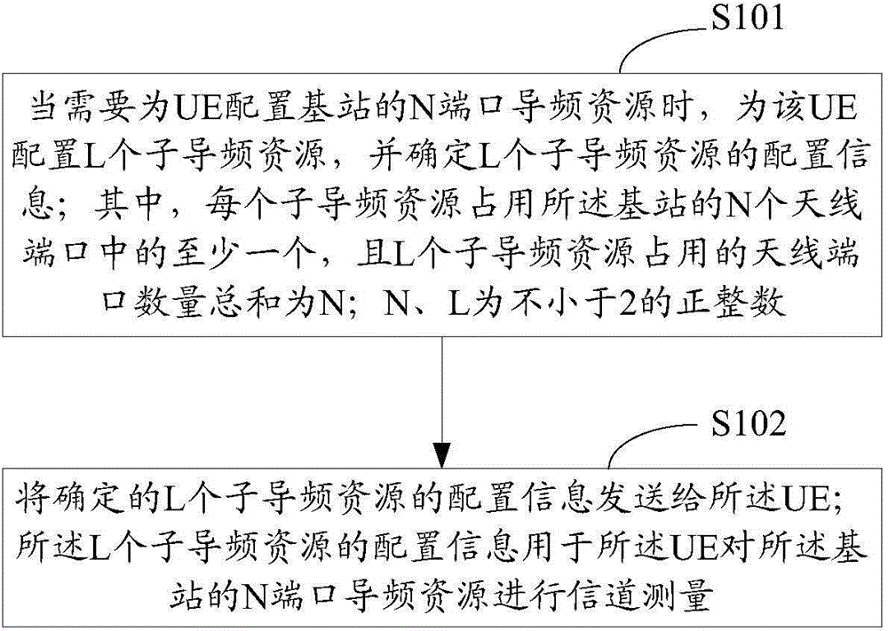
[0090] Such as figure 1 As shown, the flow chart of the channel measurement method provided by Embodiment 1 of the present invention includes the following steps:
[0091] S101: When it is necessary to configure the N-port pilot resources of the base station for the UE, configure L sub-pilot resources for the UE, and determine the configuration information of the L sub-pilot resources; wherein, each sub-pilot resource occupies the N port of the base station. At least one of the antenna ports, and the sum of the number of antenna ports occupied by the L sub-pilot resources is N; N and L are positive integers not less than 2.
[0092] In specific implementation, when it is necessary to configure the N-port pilot resource of the base station for the UE, according to the size of the N value, choose to configure one pilot resource or configure multiple sub-pilot resources, for example, if the N value is less than or equal to 8 , you can configure a pilot resource that occupies N a...
Embodiment 2
[0134] Such as image 3 As shown, it is a flow chart of the channel measurement method provided by Embodiment 2 of the present invention. This Embodiment 2 is introduced from the perspective of the UE side. The specific content that has been described in the above Embodiment 1 will not be repeated in this embodiment, including The following steps:
[0135] S301: Receive configuration information of L sub-pilot resources; wherein, each sub-pilot resource occupies at least one of the N antenna ports of the base station, and the total number of antenna ports occupied by the L sub-pilot resources is N, and N and L are A positive integer not less than 2.
[0136] Here, the configuration information of each sub-pilot resource includes one or more of the following information:
[0137] Index l of sub-pilot resources, where 1<=l<=L; resource index of sub-pilot resources; transmission power information; transmission period; subframe offset; port number information; used to indicate dif...
Embodiment 3
[0147] Such as Figure 4 As shown, the flow chart of the channel measurement method provided by Embodiment 3 of the present invention includes the following steps:
[0148] S401: When the base station needs to configure an N-port pilot resource for the UE, configure L sub-pilot resources for the UE, and determine the configuration information of the L sub-pilot resources; wherein, each sub-pilot resource occupies the N port of the base station. At least one of the antenna ports, and the sum of the number of antenna ports occupied by the L sub-pilot resources is N; N and L are positive integers not less than 2.
[0149] S402: The base station sends the determined configuration information of the L sub-pilot resources to the UE.
[0150] S403: The UE receives configuration information of L sub-pilot resources; wherein, each sub-pilot resource occupies at least one of the N antenna ports of the base station, and the total number of antenna ports occupied by the L sub-pilot resou...
PUM
 Abstract
Description
Claims
Application Information
 - Generate Ideas
- Intellectual Property
- Life Sciences
- Materials
- Tech Scout
- Unparalleled Data Quality
- Higher Quality Content
- 60% Fewer Hallucinations
Browse by: Latest US Patents, China's latest patents, Technical Efficacy Thesaurus, Application Domain, Technology Topic, Popular Technical Reports.
© 2025 PatSnap. All rights reserved.Legal|Privacy policy|Modern Slavery Act Transparency Statement|Sitemap|About US| Contact US: help@patsnap.com


