
Self-recovery method for test failure of optical module at otdr transmitter

An optical module testing and self-recovery technology, applied in the field of optical communication networks, can solve problems such as transmitter failure and excessive received light, and achieve the effect of reducing later maintenance costs and handling accidental failures easily.

Active Publication Date: 2018-05-25
四川泰瑞创通讯技术股份有限公司
View PDF3 Cites 0 Cited by
  • Summary
  • Abstract
  • Description
  • Claims
  • Application Information

AI Technical Summary

Problems solved by technology

[0005] The purpose of the present invention is to provide a self-recovery method for the transmitting end to solve the above-mentioned problem that the optical module will fail due to too strong received light in the OTDR test

Method used


Image

  • Self-recovery method for test failure of optical module at otdr transmitter
  • Self-recovery method for test failure of optical module at otdr transmitter
  • Self-recovery method for test failure of optical module at otdr transmitter

Examples


Embodiment Construction

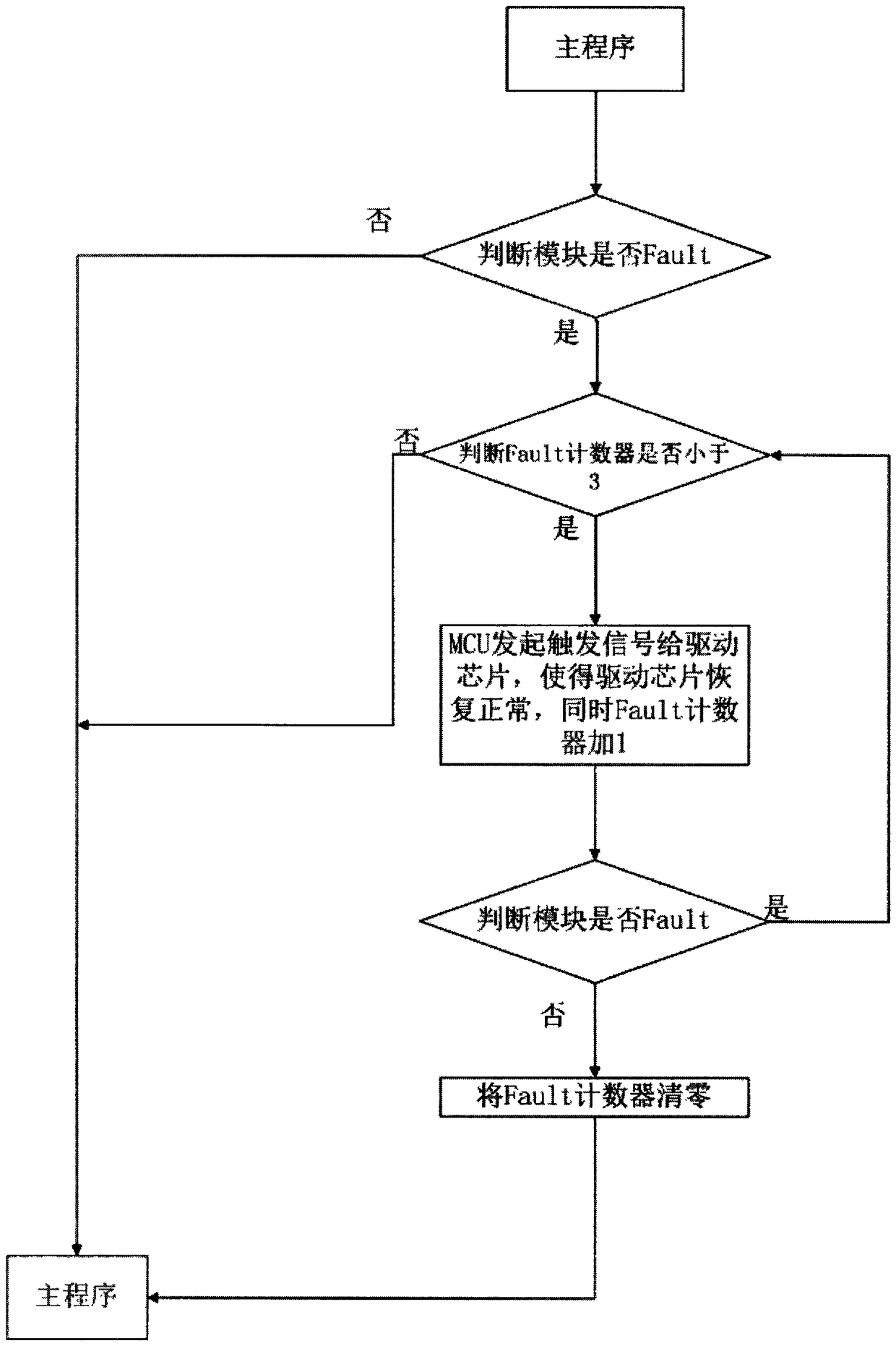
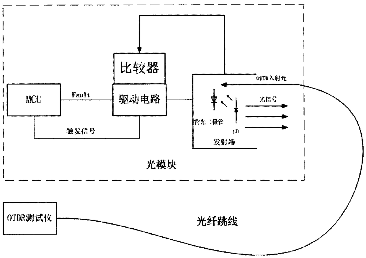
[0015] refer to figure 1 . In the embodiment described below, the specific steps of the self-recovery of the OTDR transmitter optical module test failure: the micro-control unit MCU that contains the self-recovery program software is set in the optical module, and the micro-control unit MCU is connected to the Fault pin of the driver chip. The signal is polled. If the MCU reads that the state of the Fault pin connected to the driver chip is low, it means that the optical module is working normally. The MCU does not do any processing and continues the main program; if the Fault pin is detected If the status is high, it means that the optical module fails to work. The next step self-recovery program detection judges whether the Fault counter is less than 3, if the Fault counter is greater than or equal to 3, then return to the main program and continue to execute other instructions; if the Fault counter is less than 3, the micro control unit MCU generates a The high-level tri...


PUM


Abstract

The invention discloses a self-recovery method for the failure of the transmitting end of the optical module in the OTDR test, aiming to provide an application of self-recovery after the laser is turned off due to the self-protection of the transmitting end of the optical module in the OTDR test. The present invention is realized through the following technical solutions: a micro-control unit MCU containing self-recovery program software is set in the optical module, and the working status of the optical module is polled. When the self-recovery program detects that the optical module is in a fault state, Judging whether the Fault counter is less than 3, it will automatically enter the interrupt program, and the MCUI / O port will generate a high-level trigger signal to the driver chip, and at the same time add 1 to the Fault counter to restore the normal operation of the driver chip at the transmitting end of the optical module; if it is greater than 3, Then it does not enter the interrupt program and continues to execute the main program. The present invention clears accidental fault states through the self-recovery function of the optical module itself, which neither affects the normal use of the optical module, but also reduces the post-maintenance cost of the system operator and the optical module manufacturer.

Description

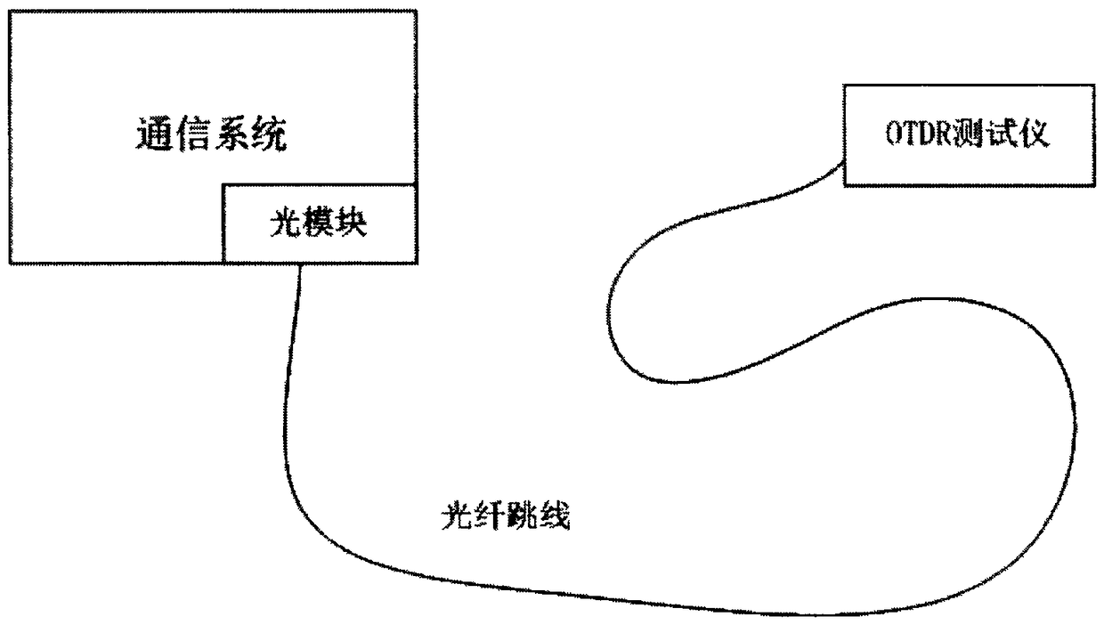
technical field [0001] The invention relates to a self-recovery method for a transmitting end of an optical module in the field of optical communication networks when the conventional optical time domain reflectometer (OTDR) test is performed. Background technique [0002] Optical cable is the main medium for transmitting information in modern wired communication. The stability and reliability of optical fiber work become the key to the normal operation of optical communication network. With the development of the times, the society's demand for data transmission is advancing by leaps and bounds. The current hardware equipment can no longer meet the demand for data volume, so it is required to continuously lay hardware facilities to meet the increasing demand. As the optical communication network becomes larger and larger, it is inevitable that the optical fiber will be broken during use. The broken optical fiber will first be reflected on the client, the network will be int...

Claims


Application Information

Patent Timeline
Patent Type & Authority Patents(China)
IPC IPC(8): H04B10/071H04B10/03
Inventor 邓彬
Owner 四川泰瑞创通讯技术股份有限公司
Learn More