
Power conversion circuit system

A technology of power conversion circuit and conversion circuit, which is applied in the direction of control/regulation system, output power conversion device, electrical components, etc., can solve the problems of not considering the circulation current and the reduction of conversion efficiency, and achieve the improvement of power conversion efficiency and circulation current reliable effect

Active Publication Date: 2016-10-05
TOYOTA JIDOSHA KK
View PDF5 Cites 3 Cited by
  • Summary
  • Abstract
  • Description
  • Claims
  • Application Information

AI Technical Summary

Problems solved by technology

[0005] In such a power conversion circuit with multiple ports, there is a possibility that circulating currents that do not contribute to power transmission may occur due to error components such as deadtime and voltage fluctuations, but this has not been considered in the prior art. Circulating current, as a result, there is a problem that the conversion efficiency decreases due to the generation of circulating current

Method used


Image

  • Power conversion circuit system
  • Power conversion circuit system
  • Power conversion circuit system

Examples


Embodiment Construction

[0024] Embodiments of the present invention will be described below based on the drawings.

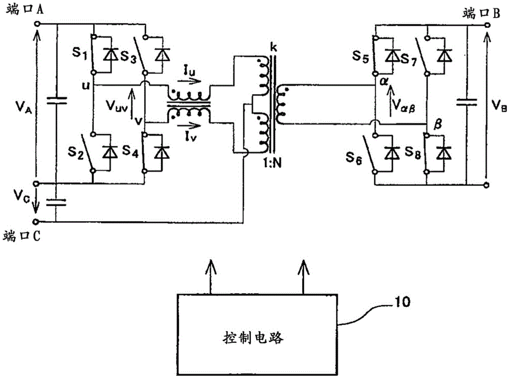
[0025] figure 1 It is a circuit configuration diagram of the power conversion circuit system in this embodiment. The power conversion circuit system is composed of a control circuit 10 and a power conversion circuit 12 . The power conversion circuit 12 is a three-port multi-port circuit capable of bidirectional power transmission between three DC power sources using magnetically coupled reactors.

[0026] The multi-port circuit includes port A and port C in the primary conversion circuit, and port B in the secondary conversion circuit.

[0027] Between the positive bus bar of the primary side conversion circuit and the negative bus bar of the primary side conversion circuit, switching transistors S connected in series with each other are arranged. 1 and S 2 constitutes the left arm and consists of switching transistors connected in series with each other S 3 and S 4 These left an...


PUM


Abstract

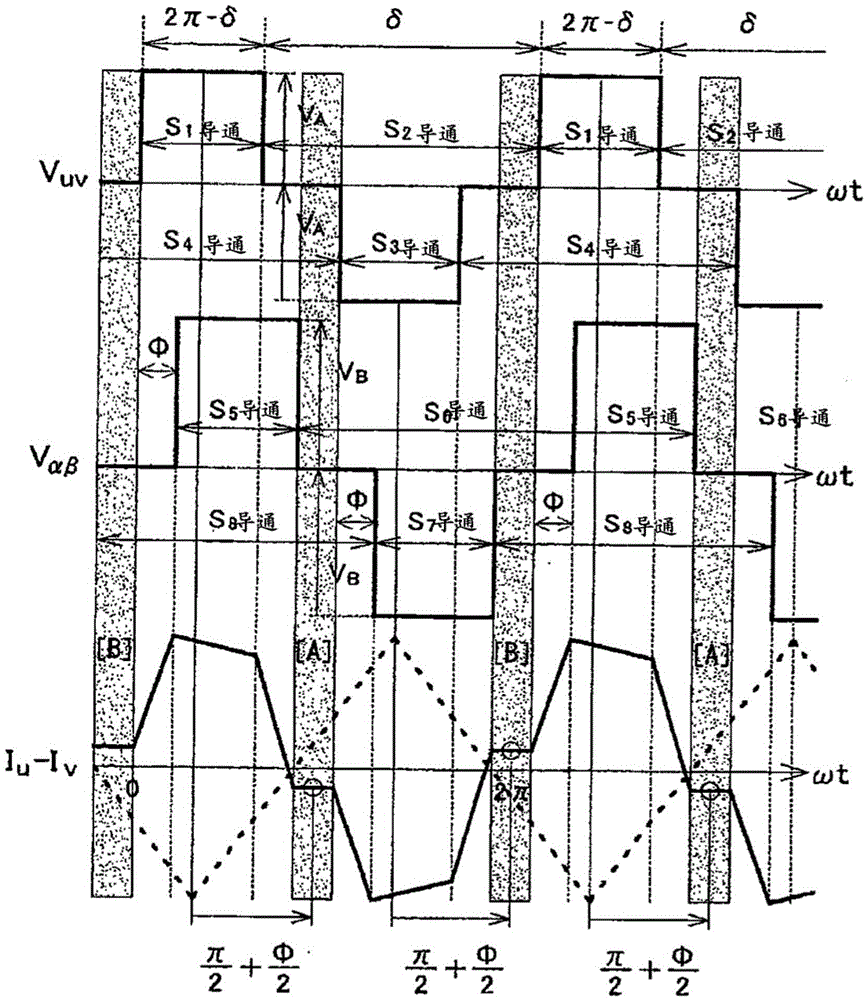
The present invention provides a power conversion circuit system in which a circulating current can be reduced by accurately detecting the circulating current, to thereby improve efficiency in power conversion. The power conversion circuit system includes a power conversion circuit composed of a primary conversion circuit having left and right arms and a secondary conversion circuit having left and right arms, and a control circuit for controlling switching of switching transistors in the primary and secondary conversion circuits. The control circuit detects the circulating current at at least one of timings lagged by pi / 2+phi / 2 from at least either a peak timing or a valley timing in a carrier counter where phi represents a difference in phase between the primary and secondary conversion circuits, and performs feedback control for reducing the detected circulating current to zero.

Description

technical field [0001] The present invention relates to a power conversion circuit system, in particular to a power conversion circuit system with a plurality of input and output ports. Background technique [0002] With the development and popularization of electric vehicles such as hybrid vehicles, electric vehicles, and fuel cell vehicles, there is a tendency for in-vehicle power supply circuits to become more complex and larger. For example, in a hybrid vehicle, there are a running battery, a system battery, an external power supply circuit for plug-in, a DC / DC converter for supplying DC power from the running battery to a running motor, DC / AC converters for converting the DC power of the running battery to AC power, DC / DC converters for supplying the DC power of the running battery to electric power steering (EPS), The structure of the DC / DC converter that supplies the direct current power to the auxiliary equipment is complex. [0003] Therefore, the development of a...

Claims


Application Information

Patent Timeline
IPC IPC(8): H02M3/335
CPCH02M3/335H02M3/33584H02M1/0009H02M3/33546H02M1/08
Inventor 井上俊太郎高木健一杉山隆英长下贤一郎冈村贤树新见嘉崇
Owner TOYOTA JIDOSHA KK
Learn More