An electronic sight for parabolic trajectory

An aimer and electronic technology, which is applied in the field of electronic aimers, can solve the problems of inability to correct background data, large errors, and inability to see the process.

Active Publication Date: 2018-10-16
GUIZHOU JINGHAO TECH
View PDF3 Cites 0 Cited by
  • Summary
  • Abstract
  • Description
  • Claims
  • Application Information

AI Technical Summary

Problems solved by technology

[0007] There are two technical defects in prior art 1 and prior art 2. First, the ballistic curves and corresponding values ​​of different bullets are re-stored in the memory for users to call. It seems that direct call storage is simple and practical, but in the actual application environment , due to the wide variety of weapons, roughly divided into guns and guns, their ballistic curves are obviously different, and they are also affected by the interference of external factors. For example, the same wind has obviously different effects on the ballistics of different weapons. Therefore, through The simple way of storing data in the memory and calling it has large errors in practical applications, and it is basically impossible to hit the target accurately; secondly, although the display components in the prior art can display the target pattern, they cannot accurately display the ballistic curve , and the whole process of simulating hitting the target, the observation is like after shooting the target at the shooting range, using a telescope to observe whether the target is hit, only the result can be seen, but the process cannot be seen, because the entire shooting process cannot be recorded and observed , that is, the difference between the actual shooting trajectory and the simulated trajectory cannot be known, and the background data cannot be corrected

Method used


Image

  • An electronic sight for parabolic trajectory
  • An electronic sight for parabolic trajectory
  • An electronic sight for parabolic trajectory

Examples


Embodiment Construction

[0033] In order to make the object, technical solution and advantages of the present invention clearer, the present invention will be further described in detail below in conjunction with specific embodiments and with the accompanying drawings and tables.

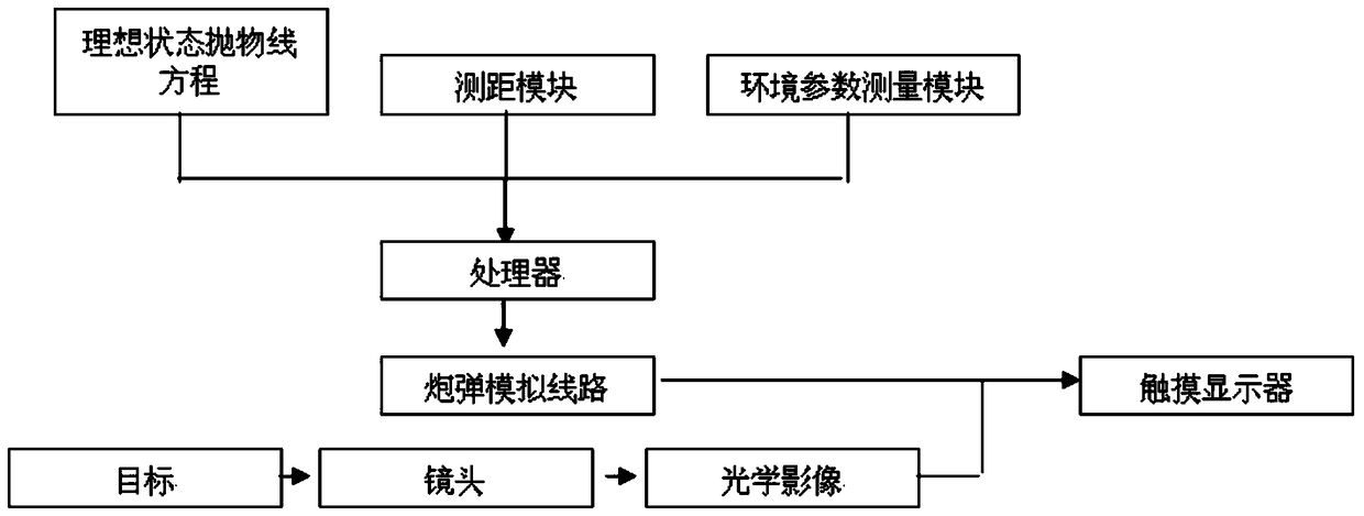
[0034] The electronic sight of the present invention includes a bracket, a lens, a touch display screen, and a processor, the bracket is detachably fixed on the firearm, the lens captures the optical image of the aimed target, and the touch screen is used to receive After the user's operation instruction, the information is sent to the processor, and at the same time, the simulated route of the shell and the optical image of the aimed target can be displayed at the same time. The electronic sight also includes a straight line for measuring the aimed target and the sight. A ranging module for distance and level difference, and the electronic sight also includes an environmental parameter measurement module for obtaining ambie...


PUM


Abstract

The invention provides an electronic sighting device used for parabolic ballistic trajectories. On one hand, a processor calculates the simulated paths of cannonballs in ideal states according to linear distances, horizontal height differences, environmental temperatures, wind power, wind power parameters and cannonball models. On the other hand, the processor searches mapping tables among the cannonball models, the environmental temperatures, the wind power, the wind power parameters and offsets and determines offsets under corresponding environmental conditions. Then, the simulated paths of the cannonballs are determined according to the fitting of parabolic equations in ideal states and the offsets, and a touch display screen is controlled to simultaneously display the simulated paths of the cannonballs and the optimal images of sighted targets. According to the electronic sighting device, the simulated paths of the cannonballs are determined through fitting a numerical calculation mode and a table searching mode, ballistic trajectory calculating efficiency and precision are greatly improved, and the real-time generation of the corresponding parabolic ballistic trajectories can be basically realized.

Description

technical field [0001] The invention relates to an aiming device, in particular to an electronic sight for parabolic ballistics. Background technique [0002] In order to improve the efficiency and accuracy of shooting, people have invented various instruments and equipment to help users aim the gun at the target for many years. There are many aiming equipment for guns. Briefly speaking, the common ones are divided into two types: Telescopic Sight and Reflex Sight. There are also sights designed based on other principles. The sighting instruments focus on solving different aspects. [0003] A sight, one of its cores, is to help users hit potential targets accurately, conveniently, and quickly. [0004] A sight, at its other core, enables the user to see potential targets clearly. [0005] Prior Art 1 [CN201010511597] discloses an electronic sight, which consists of a lens, an image sensor, a processor, a memory, a display and a touch screen. First of all, the combination...

Claims


Application Information

Patent Timeline
Patent Type & Authority Patents(China)
IPC IPC(8): F41G1/46
Inventor 李貌李丹阳龚亚云
Owner GUIZHOU JINGHAO TECH
Why Eureka
Try Eureka