Manual puncture guider
A guiding instrument and hand-held technology, applied in the field of hand-held puncture guiding instruments, can solve the problems of patient pain, inconvenience in use, inaccurate needle insertion, etc., and achieve the effect of shortening operation time and being convenient to use.
- Summary
- Abstract
- Description
- Claims
- Application Information
AI Technical Summary
Problems solved by technology
Method used
Image

Examples
Embodiment 1
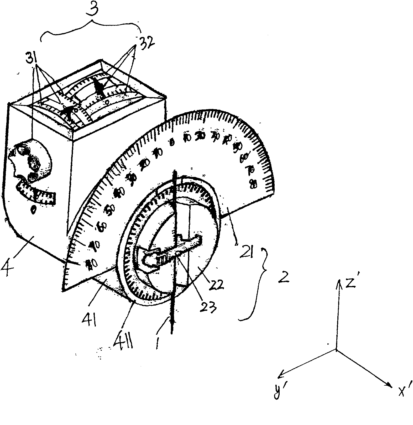
[0085] Such as image 3 , Figure 4 As shown, the present invention generally includes three parts: a frame 4, a clamping guide assembly 2 arranged at the end of the frame 4, and a rotatable alignment assembly 3 arranged inside the frame 4, wherein the alignment assembly 3 is It includes: an alignment assembly 31 of the puncture level and an alignment assembly 32 of the needle insertion reference. The alignment rotation axis of the alignment assembly 31 on the puncture level is perpendicular to the adjustment rotation axis of the puncture needle, and the alignment rotation axis of the alignment assembly 32 on the needle insertion reference is parallel to the adjustment rotation axis of the puncture needle.
[0086] The specific structure of each component of this embodiment and the specific connection relationship between each component will be described in detail below.
[0087] 1. The positioning guide assembly of the puncture needle 2
[0088] Such as image 3 , Figur...
Embodiment 2
[0134] The difference between this embodiment and the first embodiment is that the fastening adjustment part in the fourth embodiment adopts a post type fastening adjustment part. Such as Figure 8 , in the radial direction of the needle seat 22, there is an open cylindrical guide groove 241, the longitudinal direction of the cylindrical guide groove 241 is parallel to the plane where the angle indexing plate 21 is located; it matches the cylindrical guide groove 241 What’s more, the plug-type fastening adjustment assembly is also provided with a cylindrical guide seat 242 that can accommodate the puncture needle, and the outer diameter D of the cylindrical guide seat 242 is 2 Equal to the inner diameter D of the cylindrical guide groove 241 1 ; In order to fix the puncture needle, a cylindrical guide groove 243 leading to it is also provided in the axial direction of the cylindrical guide seat 242; the diameter d of the guide groove 243 2 According to the outer diameter d o...
Embodiment 3
[0139] Different from the first embodiment, the rotary indexing plate 21 is detachably fixed to the end 41 of the machine base 4 in a plug-in manner.
[0140] Such as Figure 9 As shown: there is a slot 413 on the upper side of the end 41 of the base 4. Correspondingly, the angle index plate 21 is ring-shaped, and a plug 215 matching the slot 413 is provided at the lower end of the inner ring. , the size, shape, and position of the two match, and the inner diameter of the rotary index plate 21 is equal to the outer diameter of the end portion 41 of the base. When the angle indexing plate 21 is in use, the inserting block 215 can be inserted into the slot 413 to realize fixing; when not in use, the angle indexing plate 21 can be pulled out from the slot 413 .
[0141] The needle seat 22 is directly pivoted on the end surface of the base 4 . The connection method in Embodiment 1 can be used between the two, and the bearing connection can also be used.
[0142] In order to imp...
PUM
 Abstract
Description
Claims
Application Information
 - R&D
- Intellectual Property
- Life Sciences
- Materials
- Tech Scout
- Unparalleled Data Quality
- Higher Quality Content
- 60% Fewer Hallucinations
Browse by: Latest US Patents, China's latest patents, Technical Efficacy Thesaurus, Application Domain, Technology Topic, Popular Technical Reports.
© 2025 PatSnap. All rights reserved.Legal|Privacy policy|Modern Slavery Act Transparency Statement|Sitemap|About US| Contact US: help@patsnap.com