Anti-mistake electronic padlock

An electronic and anti-mistake technology, applied in padlocks, building locks, non-mechanical transmission-controlled locks, etc., can solve problems such as large functional limitations, low reliability, and limited precision, and achieve the effect of simple structure and high reliability

Active Publication Date: 2019-02-05
ZHUHAI UNITECH POWER TECH CO LTD
View PDF7 Cites 0 Cited by
  • Summary
  • Abstract
  • Description
  • Claims
  • Application Information

AI Technical Summary

Problems solved by technology

However, traditional mechanical locks and unlocking devices usually adopt a contact connection structure, which has disadvantages such as low safety, high failure rate, and large functional limitations.
[0003] With the development of power equipment, the traditional single locking method can no longer meet the needs, and there are more and more applications that require comprehensive locking methods, and locking devices with both mechanical and electrical locking functions are required
At the same time, traditional locking devices are gradually no longer suitable for new anti-mislocking occasions due to backward technology and limited precision.
[0004] Although the existing electronic padlocks meet the functions of electromechanical locking, the existing electronic padlocks all have the problems of complex structure and low reliability.

Method used


Image

  • Anti-mistake electronic padlock
  • Anti-mistake electronic padlock
  • Anti-mistake electronic padlock

Examples


Embodiment 1

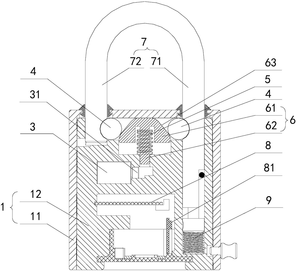
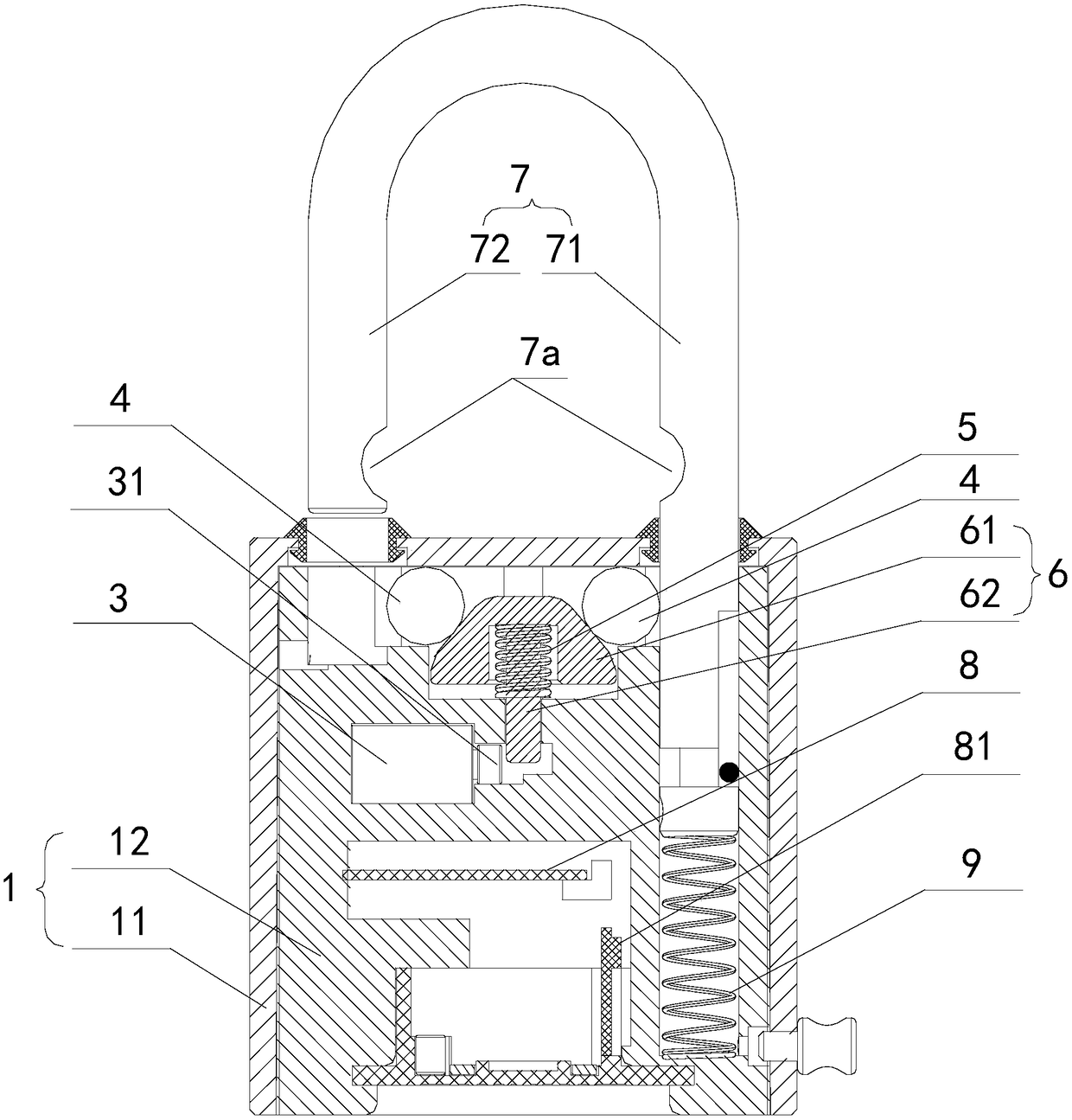
[0049] Such as figure 1 As shown, the anti-mistake electronic padlock in Embodiment 1 of the present invention includes: a lock body 1, a lock hook 7, an electronic locking mechanism and an internal circuit 8, wherein the lock body 1 includes a lock case 11 and a lock located in the lock case 11 mount 12. The lock body 1 in this embodiment adopts a split structure, the lock housing 11 can be made of relatively hard metal material, and the mounting seat 12 can be made of plastic material, so that various mounting holes / grooves can be processed on the mounting seat 12 conveniently.

[0050] The lock hook 7 is movably mounted on the lock body 1, and the lock hook 7 can move back and forth between an unlocked position and a locked position. The lock hook 7 includes a long hook arm 71 and a short hook arm 72, Both the long hook arm 71 and the short hook arm 72 are provided with a semicircular first limiting groove 7a. A fifth elastic component 9 is installed between the long hook...

Embodiment 2

[0059] Such as Figure 5-8 As shown, the structure of the anti-mistake electronic padlock in the second embodiment of the present invention is generally the same as that in the first embodiment, the difference is that the bolt mechanism in the second embodiment includes two locking blocks 13, a limit block 14, a push The rod assembly 15 and the third elastic part 16, wherein the two locking blocks 13 are arranged side by side along the same straight line, and can move back and forth between the engaging position and the non-engaging position, and the two locking blocks 13 are far away from each other. One end of the V-shaped deadbolt 13a is provided, and the long hook arm 71 and the short hook arm 72 are provided with a V-shaped first limiting groove 7a that cooperates with the V-shaped deadbolt 13a, and the first elastic member 5 is arranged on two Between the adjacent ends of the locking block 13 . When the lock hook 7 is in the locked position, the lock tongue 13a is oppos...

Embodiment 3

[0066] Such as Figure 9-11 As shown, the structure of the anti-malfunction electronic padlock in the second embodiment of the present invention is generally the same as that in the first embodiment, the difference is that the bolt mechanism in the third embodiment includes two locking blocks 13, wherein the two locking blocks The blocks 13 are arranged side by side along the same straight line, and can move back and forth between the engaging position and the non-engaging position. One end of the two locking blocks 13 far away from each other is provided with a V-shaped deadbolt 13a, a long hook arm 71 and a short hook arm 71. The hook arms 72 are each provided with a V-shaped first limiting groove 7a matched with the V-shaped locking tongue 13a, and the first elastic member 5 is arranged between the two close ends of the locking blocks 13 . The limit pin 31 of the electronic drive element 3 is located between the two locking blocks 13. When the limit pin 31 is extended, the ...


PUM


Abstract

The invention discloses an anti-error electronic padlock which comprises a lock body, a lock hook, an electronic blocking mechanism and an internal circuit, wherein the lock hook is moveably arranged on the lock body; the lock hook can move back and forth between an unlocking position and a locking position; a first limiting slot is formed on the lock hook; the electronic blocking mechanism is arranged in the lock body; the internal circuit is arranged in the lock body and is connected with the electronic blocking mechanism; the electronic blocking mechanism comprises a spring bolt mechanism and an electronic driving element; the spring bolt mechanism comprises a spring bolt capable of moving back and forth between a blocking position and a non-blocking position; the spring bolt is matched with the first limiting slot; the electronic driving element is connected with a driving signal output end of the internal circuit; the electronic driving element is provided with a stretchable limiting pin; when the limiting pin of the electronic driving element stretches out, the limiting pin limits the motion of the spring bolt; when the internal circuit controls the limiting pin of the electronic driving element to retract, the limiting to the spring bolt is released by the limiting pin. The anti-error electronic padlock provided by the invention has the advantages of simple structure and high reliability.

Description

technical field [0001] The invention relates to a lock, in particular to a misuse-preventing electronic padlock. Background technique [0002] In order to prevent human operation accidents, microcomputer anti-misoperation locking systems are commonly used in substations and power plants to lock operating equipment. The purpose of the locking devices used is to prevent human misoperation. However, traditional mechanical locks and unlocking devices usually adopt a contact connection structure, which has disadvantages such as low safety, high failure rate, and large functional limitations. [0003] With the development of power equipment, the traditional single locking method can no longer meet the needs, and there are more and more applications that require comprehensive locking methods, and locking devices with both mechanical and electrical locking functions are required. At the same time, traditional locking devices are gradually no longer suitable for new anti-misoperatio...

Claims


Application Information

Patent Timeline
Patent Type & Authority Patents(China)
IPC IPC(8): E05B67/22E05B67/38E05B47/00G07C9/00
Inventor 常青高永昊李保福王岗刘仙
Owner ZHUHAI UNITECH POWER TECH CO LTD
Why Eureka
Try Eureka