Anchor bolt-slurry-surrounding rock bond strength test method

一种粘结强度、测试方法的技术,应用在安装锚杆、强度特性、使用施加稳定的剪切力测试材料强度等方向,达到克服剪应力分布不均匀、力学参数准确的效果

Active Publication Date: 2017-03-15
SHANDONG UNIV OF SCI & TECH
View PDF4 Cites 0 Cited by
  • Summary
  • Abstract
  • Description
  • Claims
  • Application Information

AI Technical Summary

Problems solved by technology

The uniform distribution of shear stress on the bonded surface is achieved by unfolding the anchor structure, which overcomes the technical problems of uneven shear stress transmission in the traditional anchor pull-out test, and can accurately obtain the mechanical parameters of the anchor under different conditions, providing reasonable support for underground engineering. Provide scientific basis for protection design

Method used


Image

  • Anchor bolt-slurry-surrounding rock bond strength test method
  • Anchor bolt-slurry-surrounding rock bond strength test method
  • Anchor bolt-slurry-surrounding rock bond strength test method

Examples


Embodiment 1

[0040] A method for testing the bond strength of a bolt-slurry-surrounding rock, comprising the following steps:

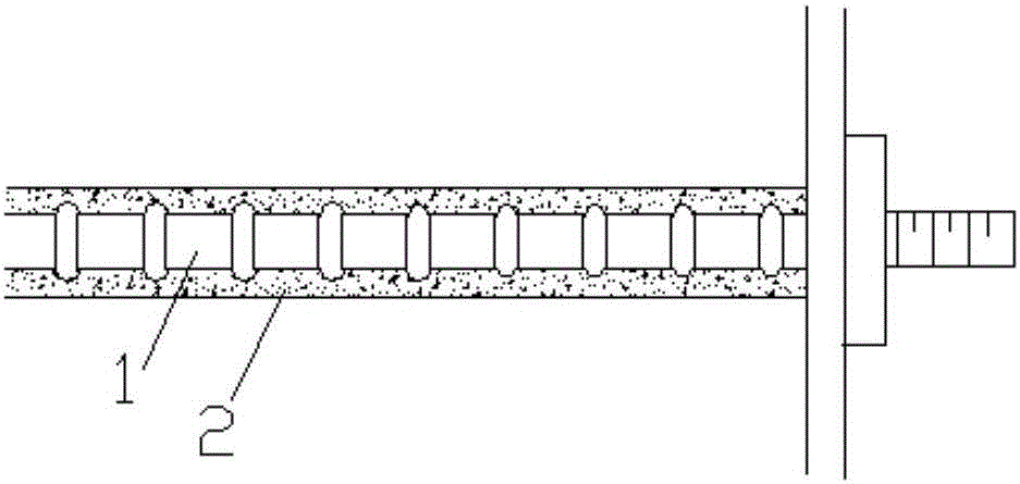
[0041] ①Take the bolt used in the project site, scan the surface of the bolt with a laser scanner, and obtain the topography data of the bolt surface;

[0042] ②Transmit the surface topography data of the anchor rod to the 3D printer, and print out the mold 5 with the surface topography of the anchor rod for making the anchor rod shear test piece 3 through the 3D printer, such as Figure 5shown;

[0043] ③Using the mold 5 as a template to make the anchor shear specimen 3, the anchor shear specimen 3 is in the shape of a cuboid as a whole, its upper surface has the same shape as the anchor surface, and the side and lower surfaces are smooth surfaces. The material is consistent with the material type of the anchor bolt on the project site;

[0044] ④Using the anchor shear test piece 3 as a template, pour the anchor bonding material on the anchor shear test piece 3...

Embodiment 2

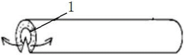
[0048] ①Cut a section of the anchor rod at the project site as the anchor rod test piece, roll the anchor rod test piece through the plastic material under the set pressure condition, and leave the surface morphology of the anchor rod on the surface of the plastic material;

[0049] ② Use the plastic material surface as a template to make the anchor shear test piece 3. The anchor shear test piece 3 is in the shape of a cuboid as a whole, its upper surface has the same shape as the anchor surface, and the side and lower surfaces are smooth. Surface, the material used is consistent with the material type of the anchor bolt on the project site;

[0050] ③Using the anchor shear test piece 3 as a template, pour the anchor bonding material on the anchor shear test piece 3 to form a slurry layer 6, the thickness of the slurry layer 6 is the same as the thickness of the slurry in the project site Consistent, after the slurry layer 6 is solidified, the rock-like material is poured to f...


PUM


Abstract

The invention relates to a method for testing the bond strength of anchor rod-slurry-surrounding rock, comprising the following steps: Step 1: making an anchor rod simulation body with a first surface, the concave-convex feature of the first surface and the side wall of the anchor rod body The surface morphology is consistent, and the first surface is a plane; step 2: pouring a slurry layer for simulating the grouting body material on the first surface of the anchor simulated body; step 3: pouring a slurry layer on the solidified slurry layer To simulate the surrounding rock layer of the surrounding rock material, the bolt simulation body, the slurry layer and the surrounding rock layer together constitute the simulated anchor; step 4: conduct a shear test along the simulated stress direction of the simulated anchor, and then obtain the reflected Mechanical parameters of bond strength. The uniform distribution of shear stress on the bonded surface is achieved by unfolding the anchor structure, which overcomes the technical problems of uneven shear stress transmission in the traditional anchor pull-out test, and can accurately obtain the mechanical parameters of the anchor under different conditions, providing reasonable support for underground engineering. Provide scientific basis for protection design.

Description

technical field [0001] The invention relates to the technical field of underground engineering, in particular to a method for testing the bonding strength of a bolt-slurry-surrounding rock. Background technique [0002] Anchor is one of the main support forms for underground engineering and rock slopes, and it is a tension member that goes deep into the formation. The technology is to drill holes in the rock or soil layer, bury the anchor rods in the drill holes, and then pour grout into the drill holes to fix the anchor rods on the rock (soil) layer of the slope or tunnel. In order to restrain the deformation and failure of the rock (soil) layer, play a supporting role. Relying on the bonding force between the grouting body and the ground in the anchorage section of the anchor rod, the gripping force of the anchor rod body and the grouting body, and the strength of the anchor rod body work together to bear the load acting on the supporting structure to maintain Stability ...

Claims


Application Information

Patent Timeline
Patent Type & Authority Patents(China)
IPC IPC(8): G01N19/04
CPCG01N19/04G01N2203/0298B33Y10/00B33Y50/00B33Y80/00E21D20/02E21D21/00G01N3/24G01B11/2518
Inventor 蒋宇静吴学震王刚李树忱王琦蔡跃
Owner SHANDONG UNIV OF SCI & TECH
Why Eureka
Try Eureka