Multi-motor electric vehicle with motors arranged in staggered manner
An electric vehicle, multi-motor technology, applied in the direction of electric power unit, control unit, power unit, etc., can solve the problem of maximum load capacity limitation, insufficient power, etc., and achieve the effect of improving power, improving traction, and reducing power consumption
- Summary
- Abstract
- Description
- Claims
- Application Information
AI Technical Summary
Problems solved by technology
Method used
Image
Examples
Embodiment 1
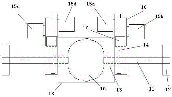
[0024] figure 1 It is a structural schematic diagram of the driven transmission gear fixed on the differential planet carrier housing. The rear axle of the electric vehicle is provided with a differential gear 10, and the left and right driven transmission gears 14 are fixed on the planetary carrier housing 13 of the differential gear, and the power of the motor unit is transmitted to the left and right transmission driven gears respectively through the transmission. On the speed change gear 14, the left and right two driven speed change gears 14 are transmitting power to the planet carrier housing 13, and the differential drives the left and right half shafts 11 to rotate.
Embodiment 2
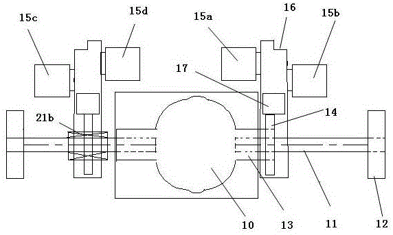
[0026] figure 2 It is a schematic diagram of the structure of a driven transmission gear fixed on the differential planet carrier housing. The rear axle of the electric vehicle is provided with a differential 10, and the differential 10 is arranged between multiple groups of motors. Among the multiple groups of motors, at least The two groups of motors are output to the differential 10 through the driven transmission gears connected to the planet carrier housing 13 of the differential 10 , the output of the differential 10 is output to the half shaft 11 , and other motor groups are indirectly connected to the half shaft 11 .
[0027] In this embodiment, the left and right two motor groups concentrate power on the driven speed change gear 14 through the speed changer, and the driven speed change gear 14 on the right side is connected with figure 1 Also fixedly connected on the planetary carrier housing 13 of the differential, the driven transmission gear 14 on the left side ut...
Embodiment 3
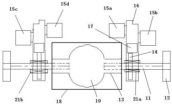
[0029] image 3 It is a schematic diagram of the structure of the driven transmission gears arranged on the axle shafts at both ends of the differential. A differential 10 is provided on the rear axle of the electric vehicle, and the differential 10 is arranged between multiple sets of motors. The output end of the differential 10 A half shaft 11 is connected to the top, and the left and right half shafts 11 are connected with a driven speed change gear 14 through a reverse locking one-way clutch. In this embodiment, the left and right half shafts 11 are respectively provided with a reverse locking one-way clutch. One 21a and reverse locking one-way clutch two 21b, each driven transmission gear is indirectly connected with a group of motors, in the present embodiment, its group of motors is motor one 15a and motor two 15b through speed changer, utilizes reverse lock Only one-way clutch one 21a is connected on the right half-shaft, and another group of motors is that motor is t...
PUM
 Abstract
Description
Claims
Application Information
 - R&D Engineer
- R&D Manager
- IP Professional
- Industry Leading Data Capabilities
- Powerful AI technology
- Patent DNA Extraction
Browse by: Latest US Patents, China's latest patents, Technical Efficacy Thesaurus, Application Domain, Technology Topic, Popular Technical Reports.
© 2024 PatSnap. All rights reserved.Legal|Privacy policy|Modern Slavery Act Transparency Statement|Sitemap|About US| Contact US: help@patsnap.com


