
False pressure head and operating method thereof

A working method and false pressure technology, applied in the direction of electrical components, printed circuit manufacturing, electrical components, etc., can solve the problems of high procurement cost and low production efficiency, achieve the effect of reducing material throwing rate, reducing procurement cost, and ensuring handover accuracy

Inactive Publication Date: 2016-09-21
BOE TECH GRP CO LTD +1
View PDF3 Cites 4 Cited by
  • Summary
  • Abstract
  • Description
  • Claims
  • Application Information

AI Technical Summary

Problems solved by technology

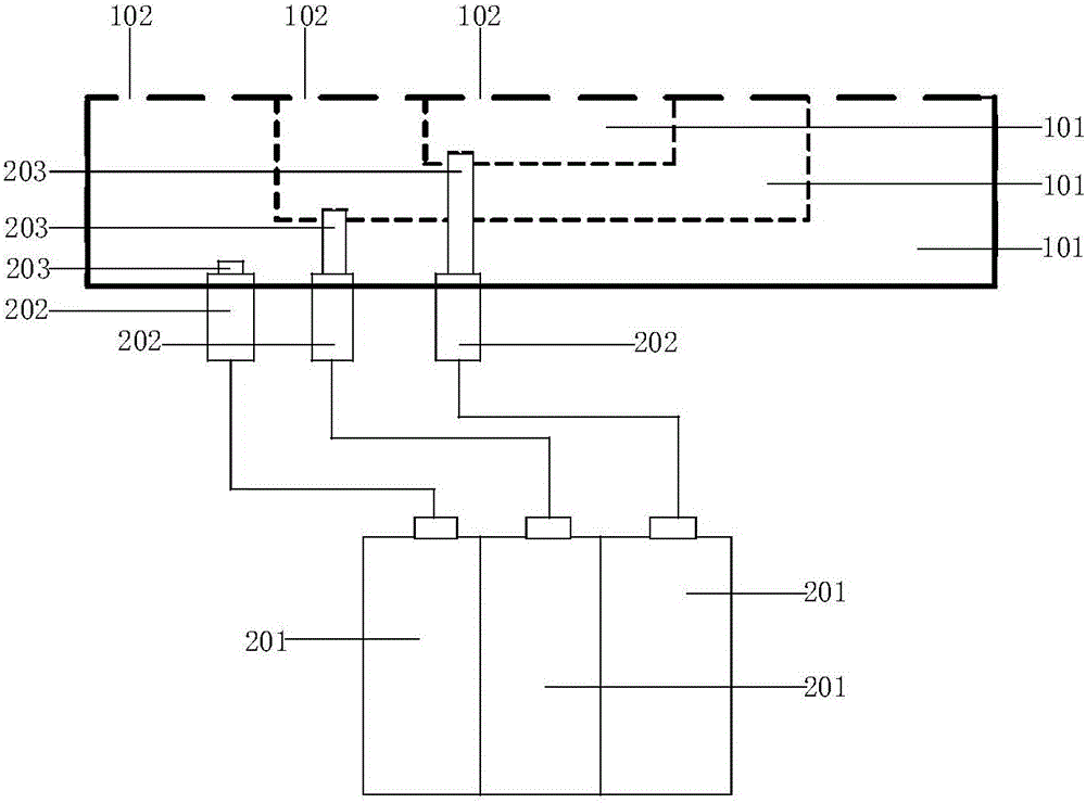
[0003] In order to solve the above problems, the present invention provides a dummy indenter and its working method, which at least partially solve the problems of low production efficiency and high purchase cost in the prior art due to the size of the circuit board that requires replacement of fixtures.

Method used


Image

  • False pressure head and operating method thereof
  • False pressure head and operating method thereof
  • False pressure head and operating method thereof

Examples


Embodiment 1

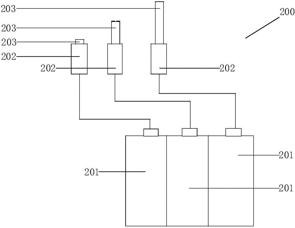
[0042] figure 1 It is a schematic structural diagram of a dummy indenter provided in Embodiment 1 of the present invention, figure 2 for figure 1 Schematic diagram of the structure of the adsorption unit shown, image 3 for figure 1 Schematic diagram of the structure of the control unit shown. Such as Figure 1-3 As shown, the dummy pressure head includes an adsorption unit 100 and a control unit, and the adsorption unit includes at least two vacuum adsorption structures, and the vacuum adsorption structure includes an air path 101 and at least one air hole 102, and the air path 101 is connected to the air hole 102. The air holes 102 are in communication. see Figure 1-2 , the number of vacuum adsorption structures is 3, and the object to be adsorbed is COF (Chip On Flex or Chip On Film, chip-on-film) or FPC (FlexiblePrinted Circuit, flexible circuit board).

[0043] In this embodiment, the control unit separately controls the formation of the vacuum environment of eac...

Embodiment 2

[0048] Figure 4 It is a flowchart of a working method of a dummy indenter provided by Embodiment 2 of the present invention. Such as Figure 4 As shown, the dummy pressure head includes an adsorption unit and a control unit, the adsorption unit includes at least two vacuum adsorption structures, the vacuum adsorption structures include an air path and at least one air hole, and the air path communicates with the air hole. The working method of described dummy indenter comprises:

[0049] Step 1001, the control unit separately controls the formation of the vacuum environment of each of the vacuum adsorption structures according to the size of the target to be adsorbed.

[0050] Step 1002, the adsorption unit performs an adsorption action on the target to be adsorbed under the control of the control unit.

[0051] see Figure 1-3 , the number of vacuum adsorption structures is 3, and the object to be adsorbed is COF (Chip On Flex or Chip On Film, chip-on-film) or FPC (Flexi...


PUM


Abstract

The invention discloses a false pressure head and an operating method thereof. The false pressure head comprises an adsorption unit and a control unit. The adsorption unit comprises at least two vacuum adsorption structures. Each vacuum adsorption structure comprises an air passage and at least one pore in communication. The control unit is used for controlling the formation of the vacuum environment of each vacuum adsorption structure according to the size of a target object to be adsorbed. The adsorption unit is used for adsorbing the target object to be adsorbed under the control of the control unit. The adsorption functions of the vacuum adsorption structures are regulated according to the sizes of circuit boards so that the false pressure head may adapt to circuit boards in different sizes. As a result, it is not required to replace a tool for false pressure head according to the size of the circuit boards, thereby achieving a universalized purpose, increasing production efficiency, reducing a reject rate of the circuit boards, and decreasing purchase cost.

Description

technical field [0001] The invention relates to the field of display technology, in particular to a dummy indenter and a working method thereof. Background technique [0002] In the display manufacturing process, the false pressing equipment is used to perform false pressing (also known as pre-pressing, false binding) of the pin circuit lines on the circuit board and the display panel. At present, there are a wide variety of products produced by module factories, and the production equipment is also different. Each product corresponds to a circuit board. Due to the different sizes of the circuit boards, a large number of fixtures need to be replaced every time the model is switched, resulting in low production efficiency and high procurement costs. The replacement of fixtures not only takes a lot of time (accounting for about 1 / 3 of the model switching time), but also easily causes other problems during the disassembly and installation process, and also brings great inconve...

Claims


Application Information

Patent Timeline
IPC IPC(8): H05K3/32
CPCH05K3/325H05K2203/0195H05K13/0069H05K3/30
Inventor 牛红林范荣华随鹏王光祥陶美艳
Owner BOE TECH GRP CO LTD
Learn More