Intelligent indoor lighting induction control method based on CAN bus

A CAN bus and control method technology, applied in the field of intelligent perception control of indoor lighting based on CAN bus, can solve problems such as waste of energy, and achieve the effects of avoiding waste, high intelligence and wide application.

Active Publication Date: 2016-09-21
BEIJING MECHANICAL EQUIP INST
View PDF5 Cites 1 Cited by
  • Summary
  • Abstract
  • Description
  • Claims
  • Application Information

AI Technical Summary

Problems solved by technology

[0004] In view of the above analysis, the present invention aims to provide a CAN bus-based indoor lighti

Method used


Image

  • Intelligent indoor lighting induction control method based on CAN bus
  • Intelligent indoor lighting induction control method based on CAN bus
  • Intelligent indoor lighting induction control method based on CAN bus

Examples


Embodiment Construction

[0042] Preferred embodiments of the present invention will be specifically described below in conjunction with the accompanying drawings, wherein the accompanying drawings constitute a part of the application and are used together with the embodiments of the present invention to explain the principle of the present invention.

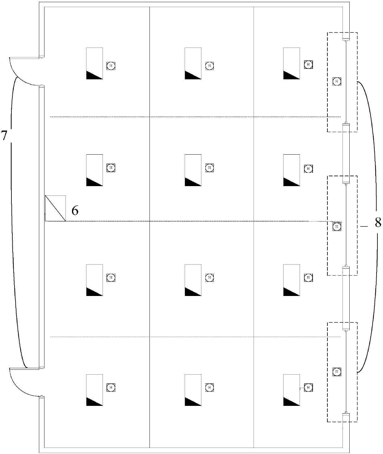
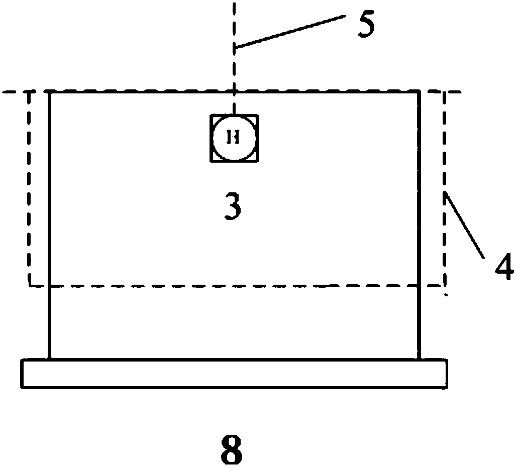
[0043] The present invention is used to control the indoor lighting of a certain room. There are three windows 8 on one side of the room, and two doors 7 on the other side. There are 12 lighting lamps 1 in the room. Column 3 lights 1.

[0044] A CAN bus-based indoor lighting intelligent perception control method, the steps of the control method are:

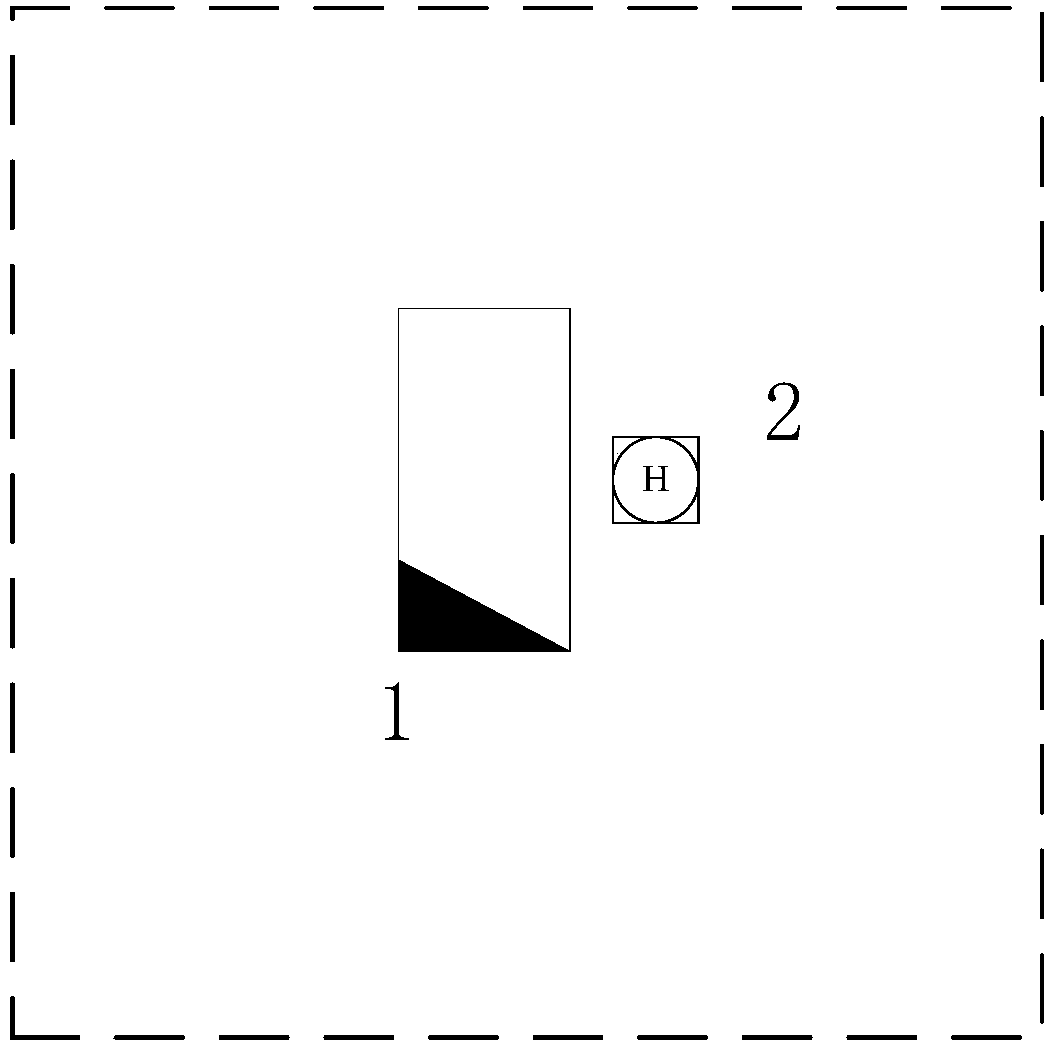
[0045] Step 1: Mesh division of the indoor lighting area. The grid of each indoor lighting area contains one indoor lighting lamp 1, and the lighting lamp is located at the center of the corresponding grid. The lighting lamp 1 is responsible for the lighting in the grid. Such as figure 1 As shown, in t...


PUM


Abstract

The invention relates to an intelligent indoor lighting induction control method based on a CAN bus. The control method comprises the steps that an indoor lighting area is subjected to grid division; a person distribution detector is arranged beside a lighting lamp in each grid; a window lighting detector is installed in front of each lighting window by a certain height; a center control system based on the CAN bus is constructed; a center control computer decision making control method is designed; an intelligent person distribution detector induction method is designed; and seventhly, function debugging is conducted. According to the method, intelligent indoor lighting induction control is achieved, various factors affecting the indoor lighting energy saving are considered, the beneficial effects that informatization is achieved, the intelligent degree is high, response is sensitive, the energy saving effect is good, and the application range is wide are achieved; and waste of indoor lighting electric energy can be effectively avoided.

Description

technical field [0001] The invention relates to the technical field of indoor lighting intelligent control, in particular to an intelligent perception control method for indoor lighting based on a CAN bus. Background technique [0002] The switch control technology of indoor lighting has been stuck in the early days of the invention of the electric light, and it has stagnated. The manual switch control method is still widely used. The application of modern information technology in this field seems to be unable to keep up with the development of the times. [0003] With the vigorous development of the modern service industry, the number of urban office buildings and office buildings is increasing day by day. Some of them belong to normal consumption, such as lighting in indoor areas with people at night, low-brightness lighting on cloudy and sunny days, and a considerable part of energy waste, such as not turning off lights in unoccupied areas at night, not turning off light...

Claims


Application Information

Patent Timeline
IPC IPC(8): F21V23/04H05B37/02
CPCF21V23/0464F21V23/0471H05B47/10Y02B20/40
Inventor 柴志林
Owner BEIJING MECHANICAL EQUIP INST
Why Eureka
Try Eureka