
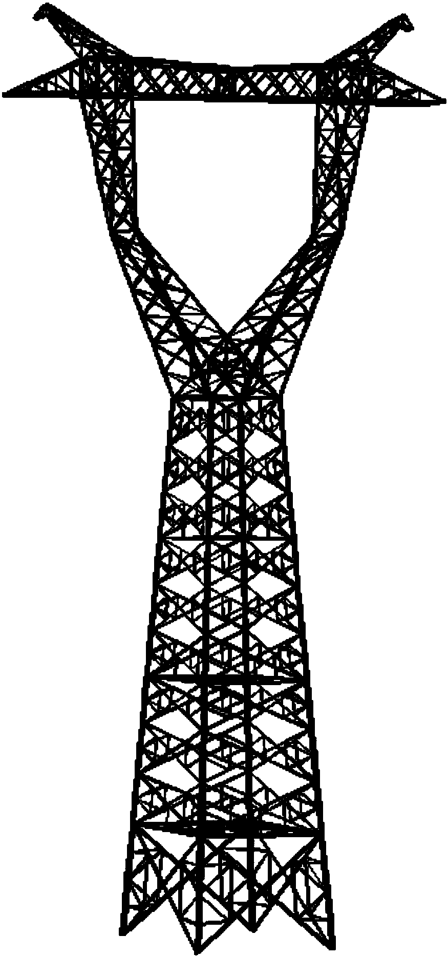
Steel Tower Angle Steel Anti-Bending and Torsional Instability Reinforcing Device

A reinforcement device, a technology of iron tower angle steel, applied in the direction of towers, building types, buildings, etc., can solve problems such as complex stress, and achieve the effects of improving compressive bearing capacity, avoiding local damage, and preventing local and overall buckling

Active Publication Date: 2018-01-09
SHANDONG UNIV
View PDF6 Cites 0 Cited by
  • Summary
  • Abstract
  • Description
  • Claims
  • Application Information

AI Technical Summary

Problems solved by technology

The angle steel in the angle steel tower is actually a two-way eccentric compression member, and its force is very complicated

Method used


Image

  • Steel Tower Angle Steel Anti-Bending and Torsional Instability Reinforcing Device
  • Steel Tower Angle Steel Anti-Bending and Torsional Instability Reinforcing Device
  • Steel Tower Angle Steel Anti-Bending and Torsional Instability Reinforcing Device

Examples


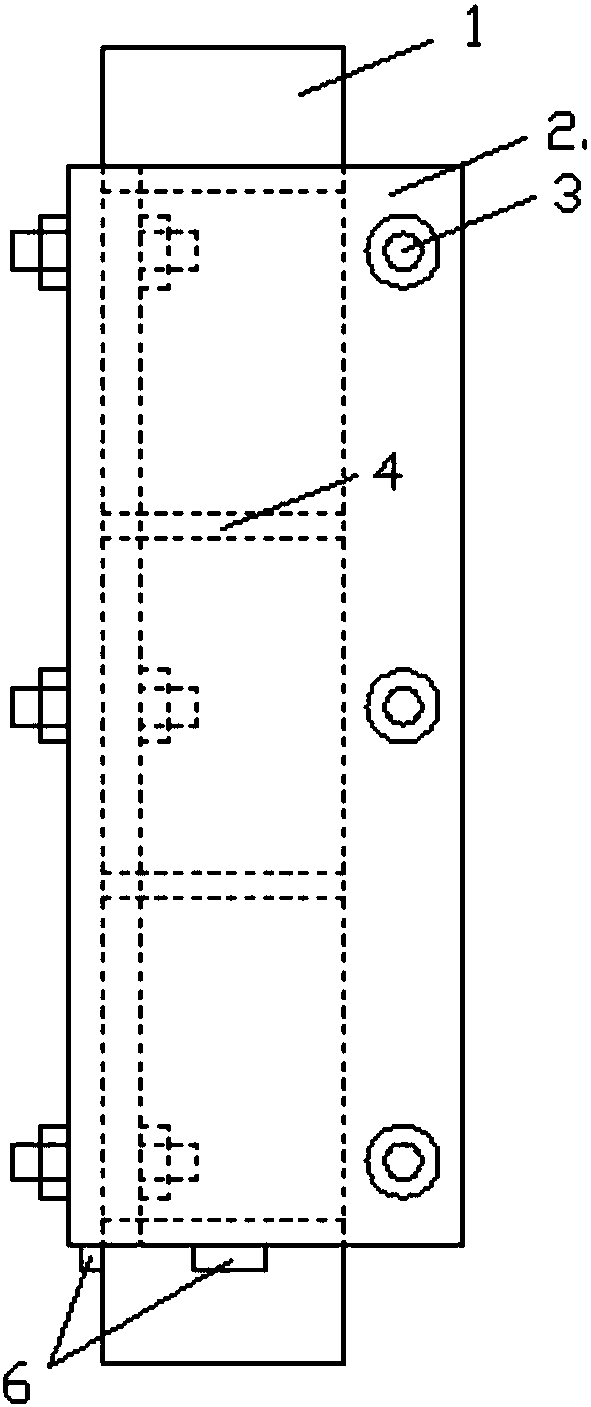
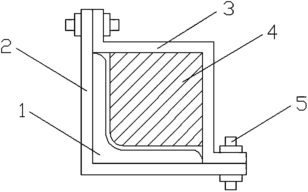
Embodiment Construction

[0027] Embodiments of the present invention will be described in detail below in conjunction with technical solutions and accompanying drawings.

[0028] Such as figure 2 , 3 Shown: The anti-bending and torsional instability reinforcement device for the angle steel of the iron tower, including the restraint member 2, the ribbed restraint member 3 and several bolts 5, the restraint member is located on the outside of the angle steel 1, its leg width is greater than that of the angle steel leg, and at the edge of its leg width Bolt holes are set; the ribbed restraint member 3 is located inside the angle steel, opposite to the restraint member 2, and ribs 4 are arranged at intervals along the length direction. The limb width of the ribbed constraining member is approximately the same as that of the angle steel leg, and a 90° corner is set at the extremity of the ribbed constraining member 3, and bolt holes are set at the corner. The restraint member and the ribbed restraint me...


PUM


Abstract

The invention discloses a reinforcement device for preventing flexural-torsional buckling of angle steel for iron towers. The reinforcement device comprises a restraint component outside the angle steel and a ribbing restraint component inside the angle steel. The restraint component is an 'L'-shaped supporting plate I, the ribbing restraint component comprises an 'L'-shaped supporting plate II, and a plurality of reinforcement rib plates with rectangular cross sections are arranged at intervals inside the 'L'-shaped supporting plate. A gap for clamping the angle steel is formed among the 'L'-shaped supporting plate I and each reinforcement rib plate, and the 'L'-shaped supporting plate I and the 'L'-shaped supporting plate II are assembled together to form an external square reinforcement device.

Description

technical field [0001] The invention belongs to the field of anti-buckling reinforcement of angle steel components, and in particular relates to a reinforcement method for preventing overall or local instability of the angle steel of iron towers such as power transmission towers or communication towers. Background technique [0002] As a lifeline project, the safety and stability of power transmission lines is related to the safety of people's lives and property. In addition, with the development of communication technology, the issue of upgrading and expanding the capacity of communication towers in service has become a top priority. At present, many transmission towers or communication towers are designed and constructed based on the technical standards, functional requirements and performance at that time. After being put into use for many years, under the new conditions of use, the load or force transmission path changes, or under the action of the external environment,...

Claims


Application Information

Patent Timeline
Patent Type & Authority Patents(China)
IPC IPC(8): E04H12/10
CPCE04H12/10
Inventor 田利郭刘潞曲冰
Owner SHANDONG UNIV
Learn More