Eureka AIR delivers breakthrough ideas for toughest innovation challenges, trusted by R&D personnel around the world.

Station-configuration method for dynamic reactive compensation apparatus capable of improving multi-feed direct current restoration capability

A multi-infeed DC and compensation device technology, applied in reactive power compensation, reactive power adjustment/elimination/compensation, power transmission AC network, etc., can solve DC commutation failure adaptability, converter station voltage fluctuation, complex and other issues to achieve the effect of avoiding large-scale search, intuitive area, and easy implementation

Inactive Publication Date: 2016-09-14
STATE GRID CORP OF CHINA +2
View PDF6 Cites 18 Cited by
  • Summary
  • Abstract
  • Description
  • Claims
  • Application Information

AI Technical Summary

Problems solved by technology

Among them, the inverter stations with long-distance DC transmission lines have the most serious problems. Due to the various control modes and operation modes of DC, it is quite complicated to find a method to evaluate the voltage stability of AC-DC systems. There are a large number of existing research results. Concentrate on the theoretical analysis stage, and there is a certain gap from the project implementation and application
[0004] However, the configuration method of the reactive power compensation device of the AC / DC system proposed for the problem of insufficient reactive power after the fault of the DC feed-in system and the voltage fluctuation of the converter station has not yet combined the configuration problem of reactive power compensation with the suppression of multi-DC commutation. failure binding analysis
Only through the simulation method to test in the multi-DC drop point area, there is not only the problem of calculation efficiency, but also the problem of adaptability to different DC commutation failures caused by different AC faults

Method used


Image

  • Station-configuration method for dynamic reactive compensation apparatus capable of improving multi-feed direct current restoration capability

Examples


Embodiment Construction

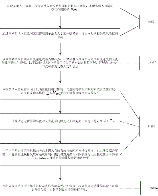
[0028] The present invention will be described in further detail below with reference to the accompanying drawings and examples.

[0029] figure 1 Step 1 in the above describes that, according to the Jacobian matrix calculated by the power flow, the interaction factors between the multi-infeed DCs are solved, and it is judged whether the corresponding interaction factors between any two DC circuits are greater than the set threshold value, so as to determine the simultaneous commutation Higher risk of failure DC.

[0030] In step 1, it is determined that the risk of commutation failure at the same time is relatively high, and the DC is carried out according to steps 1-1) to 1-2).

[0031] figure 1 As described in step 1-1, assume that the AC system at the receiving end exists L 1 , L 2 ,…, L n common n Back to the DC feed, the DC transmission power is respectively P 1 , P 2 ,…, P n . According to the Jacobian matrix calculated by the power flow, the first j Th...


PUM


Abstract

The invention discloses a station-configuration method for a dynamic reactive compensation apparatus capable of improving multi-feed direct current restoration capability, and belongs to the technical field of a power system and automation thereof. According to the method, the mutual influence between direct current systems is pre-determined through a multi-feed interaction factor index between the direct current systems; after faults are screened primarily, the direct current restoration is relatively low in speed, and tightly-linked direct current exists between the direct current systems; and the dynamic reactive optimal compensation location is determined by taking the reactive supporting capability of the dynamic reactive compensation apparatus into consideration. By adoption of the station-configuration method, the direct current restoration characteristic in the alternating current / direct current systems can be mastered in advance by an electric power system planning and operating staff so as to formulate an optimization station-configuration scheme for the dynamic reactive compensation apparatus, so that the safety, stability and the automatic level of the system are improved.

Description

technical field [0001] The invention belongs to the technical field of electric power systems and automation thereof. More precisely, the invention relates to a method for arranging dynamic reactive power compensation devices for improving multi-infeed direct current recovery capability. Background technique [0002] UHV DC transmission has the characteristics of large transmission capacity, long transmission distance and flexible and adjustable transmission power. In the operation of a multi-infeed DC system, when multiple converter stations are electrically coupled closely, a fault in the vicinity of any converter station's busbar may cause multi-infeed DC simultaneous commutation failures and are difficult to recover, and large power fluctuations may cause Disconnection or out-of-step of the power grid section, transient voltage instability of the receiving end power grid, etc., threaten the safe and stable operation of the system. [0003] At present, the research on th...

Claims


Application Information

Patent Timeline
Patent Type & Authority Applications(China)
IPC IPC(8): H02J3/36H02J3/18
CPCY02E40/30Y02E60/60H02J3/36H02J3/18
Inventor 张红丽刘福锁李威李碧君崔晓丹吕亚洲
Owner STATE GRID CORP OF CHINA
Why Eureka
Eureka Blog
Learn More