A sucker rod lifting device

A technology for lifting devices and sucker rods, which is applied to drill pipes, drilling equipment, earthwork drilling and production, etc., can solve the problems of high lifting cost, waste of manpower, low operating efficiency, etc., achieve convenient and fast lifting, reduce lifting costs, Labor saving effect

Active Publication Date: 2018-09-07
无锡世联丰禾石化装备科技有限公司
View PDF8 Cites 0 Cited by
  • Summary
  • Abstract
  • Description
  • Claims
  • Application Information

AI Technical Summary

Problems solved by technology

[0004] 1) The operation efficiency is low. In the specific operation process, it takes a lot of time to make an appointment for the crane and transport the crane to the side of the pumping well for operation, which greatly affects the normal operation of the pumping well
[0005] 2) The lifting cost of using a crane to lift the sucker rod is relatively high;
[0006] 3) Generally, multiple people are required to carry out the lifting operation, which wastes manpower

Method used


Image

  • A sucker rod lifting device
  • A sucker rod lifting device

Examples


Embodiment Construction

[0017] The technical solutions of the present invention will be further described below in conjunction with the accompanying drawings and through specific implementation methods.

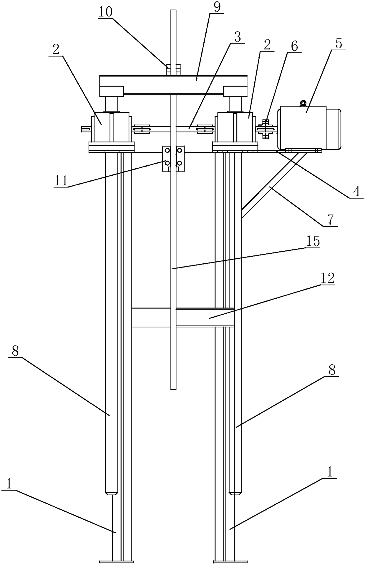
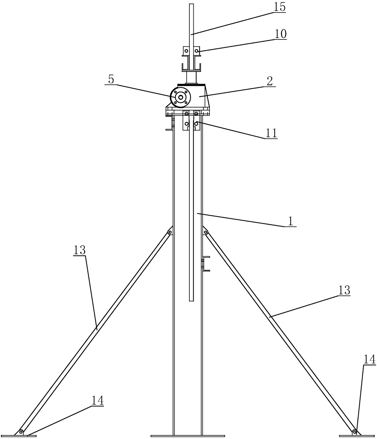
[0018] see figure 1 with figure 2 As shown, in this embodiment, a sucker rod lifting device includes two uprights 1, and the two uprights 1 are fixedly arranged on both sides of the pumping well at intervals, and the tops of the two uprights 1 are installed There is a worm gear box 2, and the worm gear shafts in the two worm gear boxes 2 are connected through the connecting shaft 3. One of the two columns 1 is provided with a mounting seat 4 to one side, and a driving motor is fixed on the mounting seat 4 5. The drive shaft of the drive motor 5 is connected to the worm gear shaft of one of the worm gear boxes 2 through a coupling 6, and the drive motor 5 drives the worm gears in the two worm gear boxes 2 to rotate synchronously. The bottom of the mounting base 4 is connected to the A support rod ...


PUM


Abstract

The invention discloses a sucker rod lifting device which comprises two stand columns. The two stand columns are fixedly arranged on the two sides of a rod-pumped well and are vertically provided with transmission rods which can vertically move along the stand columns respectively. The tops of the two transmission rods are connected with a lifting beam. The two transmission rods are connected with a drive device through a transmission assembly. An upper clamping piece is arranged in the middle of the lifting beam. A lower clamping piece is arranged between the two stand columns and below the upper clamping piece. The sucker rod lifting device is simple in structure, and lifting is convenient and rapid; two links of steam injection and oil production can be continuously switched, labor is saved, and meanwhile lifting cost of a sucker rod is greatly reduced.

Description

technical field [0001] The invention belongs to the technical field of petroleum exploitation, and in particular relates to a sucker rod lifting device capable of realizing integration of petroleum injection and production. Background technique [0002] The sucker rod is a slender rod of the pumping well, it is connected to the polished rod on the top, and the pump is connected to the bottom to transmit power. The length of a single sucker rod is 7.6 or 8 meters. The material is generally high-carbon steel plated with hard chromium. The oil pipe is connected one by one with an internal thread hoop and extends to the rotor at the underground oil layer, and the oil is pumped by rotation. . [0003] As we all know, in the process of oil exploitation, steam injection operation is carried out regularly, and the steam injection operation needs to lift the sucker rod out of the pumping well, and the current method is to use a crane to lift the sucker rod out of the pumping well A...

Claims


Application Information

Patent Timeline
Patent Type & Authority Patents(China)
IPC IPC(8): E21B19/00
CPCE21B19/00
Inventor 张瑞生蒋光潭孙月洋甘育宝
Owner 无锡世联丰禾石化装备科技有限公司
Why Eureka
Try Eureka