A plastering arm of a wall automatic semi-automatic plastering machine

A semi-automatic, plastering machine technology, applied in the field of plastering arms, can solve the problems of poor mortar adhesion, poor adaptability, and poor plastering effect, etc.

Active Publication Date: 2017-12-26
江苏九星建设工程有限公司
View PDF5 Cites 0 Cited by
  • Summary
  • Abstract
  • Description
  • Claims
  • Application Information

AI Technical Summary

Problems solved by technology

At present, in both plastering methods, it is impossible to adjust the plastering angle between the plastering board and the wall according to the actual situation, that is, the angle when plastering on the wall and the angle during calendering, and it is impossible to make the plastering board according to the actual wall. In the case of plastering, rotate around the axis perpendicular to the wall to perform horizontal and horizontal plastering. In addition, the plastering mechanisms above cannot make the plastering board have a positive elastic pressure on the wall, and the mortar attached to the wall Poor focus, when encountering small stones or raised points on the wall, there is no flexibility to back down.
This just makes the plastering board mechanism of existing miscellaneous automatic semi-automatic plastering machine poor adaptability to will carry out plastering metope, own weight is big, and plastering effect is poor

Method used


Image

  • A plastering arm of a wall automatic semi-automatic plastering machine
  • A plastering arm of a wall automatic semi-automatic plastering machine
  • A plastering arm of a wall automatic semi-automatic plastering machine

Examples


Embodiment Construction

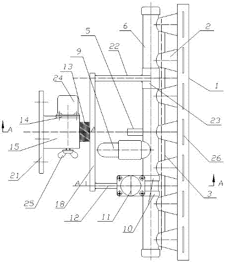
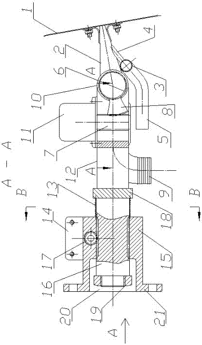
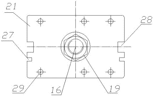
[0015] Such as Figure 1~Figure 5 It is a structural diagram of a specific embodiment of the present invention. From the figure, it can be seen that the plastering arm of the present invention includes a special-made plastering board (another application) and a plastering arm frame mechanism of a wall automatic semi-automatic plastering plastering machine. The plate surface 1 of the plastering board is rectangular, and the handle on the back side along the length direction is an ash delivery pipe. The ash delivery pipe is provided with several duckbills perpendicular to the ash delivery pipe along the length direction, and each duckbill pipe The flat outlet is connected to the corresponding mortar outlet 26 on the center line of the length direction of the rectangular plastering board surface 1, and one side of each duckbill tube 2 is connected with an air blowing pipe 4 towards the outlet direction, and each air blowing pipe 4 is connected in parallel. On the main air pipe 3...


PUM


Abstract

The invention relates to a plastering arm of an automatic and semiautomatic plastering machine of a wall surface and relates to the field of building machinery. The plastering arm comprises a special plastering plate and is characterized by further comprising a plastering arm rest mechanism; the plastering arm rest mechanism is composed of a plastering arm frame and a plastering arm seat; the plastering arm frame is provided with a linear arm and a Y-shaped arm, and the two arms are arranged at a certain interval and are parallel to each other; certain ends of two arms are vertically positioned at the two ends of a cross arm, and coaxial hoops are arranged at the other ends of the two arms; a whole plastering arm mechanism is hinged to an ash conveying pipe on the back surface of the plastering plate through the hoops; a shaft type worm wheel which is vertical to the cross arm and is opposite to the two arms is positioned in the middle of the cross arm; the shaft type worm wheel penetrates through a central hole of the plastering arm seat, is hinged to the central hole and can move along an axial direction; an axial limiting nut is screwed at the end part of the shaft type worm wheel. The plastering arm provided by the invention has the advantages of good wall surface adaptability, light self-weight, simple structure, no need of vibration, long service life, good plastering effect and strong attaching force of mortar plastered on the wall surface.

Description

technical field [0001] The invention relates to the field of construction machinery, in particular to a plastering arm of an automatic semi-automatic plastering machine for walls. Background technique [0002] In the existing various automatic and semi-automatic plastering machines, some of the plastering methods use a hose to send the mortar to a special plastering board, and then flow or spray the mortar to the wall from the ash outlet. , and then the plastering board mechanism is lifted along the vertical guide rail for plastering; some put the mortar into the ash storage hopper in advance, and the ash storage hopper has an ash outlet facing the wall, and then, while lifting the ash storage hopper along the vertical guide rail Vibration for plastering. The latter mechanism is complicated, and the load is heavy when lifting, and the body is heavy, and the machinery is very prone to failure, the plastering effect is poor, and the cost is high. The former is mainly to plas...

Claims


Application Information

Patent Timeline
Patent Type & Authority Patents(China)
IPC IPC(8): E04F21/12
CPCE04F21/12
Inventor 李德福
Owner 江苏九星建设工程有限公司
Why Eureka
Try Eureka