
Installation and vertical gap-adjusting method for crank arm beams of self-lifting outrigger rollover system of bridge pier stud

A pier column and self-elevating technology, which is applied in the direction of bridges, bridge construction, erection/assembly of bridges, etc., can solve the problems of poor installation effect and inability to install the curved arm beam 1 and the reinforced horizontal back corrugated 3, so as to speed up the installation efficiency, Easy to disassemble and improve work efficiency

Active Publication Date: 2016-09-07
CHINA 19TH METALLURGICAL CORP
View PDF7 Cites 0 Cited by
  • Summary
  • Abstract
  • Description
  • Claims
  • Application Information

AI Technical Summary

Problems solved by technology

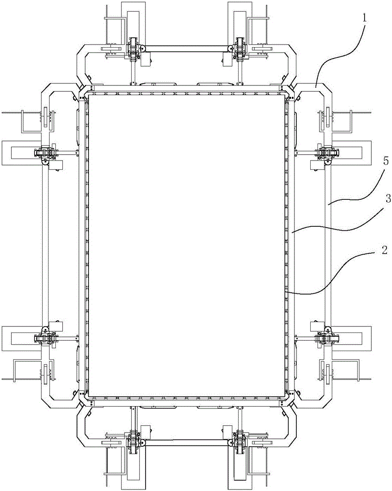
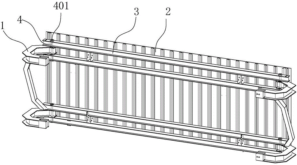
Due to the requirements of the self-elevating turning system to lift the formwork or the outer support, it is necessary to disassemble the crank beam 1 frequently. During each installation process of the crank beam 1: there may be installation errors and component deformations that may cause the crank beam 1 and strengthened horizontal back flute 3 poor installation effect, or even impossible to install

Method used


Image

  • Installation and vertical gap-adjusting method for crank arm beams of self-lifting outrigger rollover system of bridge pier stud
  • Installation and vertical gap-adjusting method for crank arm beams of self-lifting outrigger rollover system of bridge pier stud
  • Installation and vertical gap-adjusting method for crank arm beams of self-lifting outrigger rollover system of bridge pier stud

Examples


Embodiment Construction

[0026] The present invention will be further described below in conjunction with the accompanying drawings and embodiments.

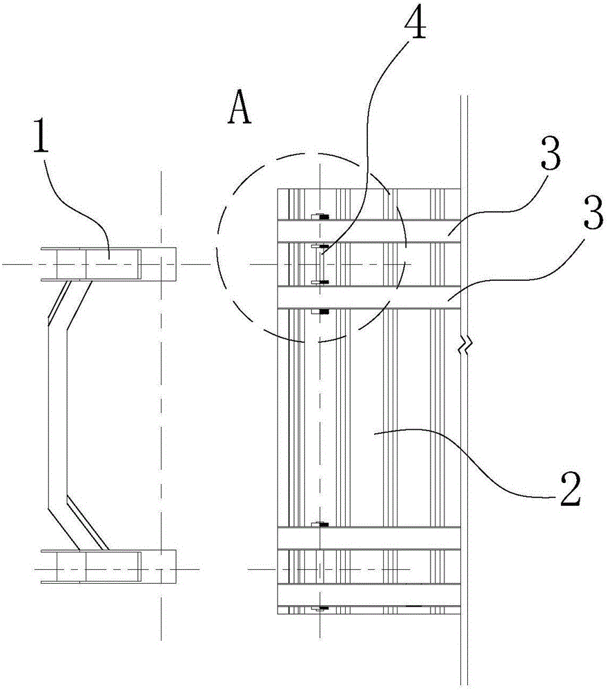
[0027] The vertical distance adjustment method for the curved arm beam installation of the bridge pier column self-elevating outer frame turning system according to the present invention is applied to the adjustment of the crank arm beam of the bridge pier column self-elevating outer frame turning system. The outer frame turning system includes a formwork 2, and the outer surface of the formwork 2 is provided with at least two reinforced transverse back flutes 3 and adjusting bolts 4; the reinforced transverse back flutes 3 have at least two, and the adjacent two Reinforced horizontal back flute 3 and parallel to each other; one end of the reinforced horizontal back flute 3 connected to the curved arm beam 1 is provided with a vertical through hole, and one end of the curved arm beam 1 connected to the reinforced horizontal back flute 3 is provided with ...


PUM


Abstract

The invention discloses an installation and vertical gap-adjusting method for crank arm beams of a self-lifting outrigger rollover system of a bridge pier stud, and the installation error between the crank arm beams and strengthening horizontal back ribs can be adjusted. The gap-adjusting method comprises the steps of 1, installing second lock nuts on the cap nut ends of adjusting bolts, the adjusting bolts penetrating a strengthening horizontal back rib, and installing second gap-adjusting nuts when the threaded ends are positioned between two adjacent strengthening horizontal back ribs; 2, when the threaded ends of the adjusting bolts penetrating vertical through holes in the crank arm beams; 3, installing first gap-adjusting nuts on the threaded ends, the threaded ends penetrating another strengthening horizontal back rib, and installing first lock nuts on the threaded ends; 4, tightening the first gap-adjusting nuts and the second gap-adjusting nuts; and 5, adjusting the first lock nuts and the second lock nuts to make the adjusting bolts to move up and down, to adjust the positions of the crank arm beams, and tightening the first lock nuts and the second lock nuts to lock the adjusting bolts. The installation efficiency can be improved by adopting the gap-adjusting method.

Description

technical field [0001] The invention relates to a vertical position adjustment method, in particular to a vertical distance adjustment method for the installation of a curved arm beam of a self-elevating outer frame turning system of a bridge pier column. Background technique [0002] The self-elevating outer frame turning system of bridge pier columns is composed of formwork system, outer support system, formwork disassembly system, lifting system, fall prevention system, operating platform system, etc., and each system is arranged in the space formed by the formwork and the support behind the formwork Inside. [0003] like figure 1 As shown, the outer support system is composed of a vertical guide beam, a curved arm beam 1, a reinforced horizontal back corrugated 3, and a straight beam 5. The curved arm beam 1, the reinforced horizontal back corrugated 3, and the straight beam 5 form a closed beam on the plane, and the components of the closed beam form a hoop-type horiz...

Claims


Application Information

Patent Timeline
IPC IPC(8): E01D21/00
CPCE01D21/00
Inventor 李炳
Owner CHINA 19TH METALLURGICAL CORP
Learn More