Image plate for rotating wheel and rotating wheel including same

A technology of rotating wheels and images, applied in the direction of wheels, wheel cover discs, tire parts, etc., can solve problems such as adverse effects of car 1 steering function, safety accidents, etc.

Inactive Publication Date: 2018-04-27
MIRYOON W&T CORP
View PDF7 Cites 0 Cited by
  • Summary
  • Abstract
  • Description
  • Claims
  • Application Information

AI Technical Summary

Problems solved by technology

[0004] However, in the process of rotating the bearings to make the wheel 20 and the image board 10 perform relative rotational motion, frictional force is generated by the internal bearing balls, and the running wind force that flows in with the running of the car 1 and the force exposed to the outside The image plate 10 is rubbed, and as image 3 As shown, a rotational force F1 will be generated in the image board 10, so that there is a problem that the non-rotating image board 10 will rotate together in the direction of rotation of the wheel 20 when the automobile 1 is running at a high speed when the vehicle is running at a low speed.
[0005] In particular, the above-mentioned counterweight 11 is arranged on the image board 10 at a position biased toward the lower part of the above-mentioned image board 10, therefore, when the above-mentioned bearing produces a malfunction and the counterweight 11 and the image board 10 rotate together, along with the counterweight 11 The eccentric load changes to generate vibration. The greater the load of the above-mentioned counterweight 11, the stronger the vibration generated. The difference in load applied to the two rotating wheels arranged on the same wheel will adversely affect the steering function of the car 1. Therefore, there are problems that can lead to safety accidents

Method used


Image

  • Image plate for rotating wheel and rotating wheel including same
  • Image plate for rotating wheel and rotating wheel including same
  • Image plate for rotating wheel and rotating wheel including same

Examples


Embodiment Construction

[0031] The purpose, characteristics, and advantages of the present invention described above will be clarified by the following detailed description. Hereinafter, the following description will be given based on the drawings showing preferred embodiments of the present invention.

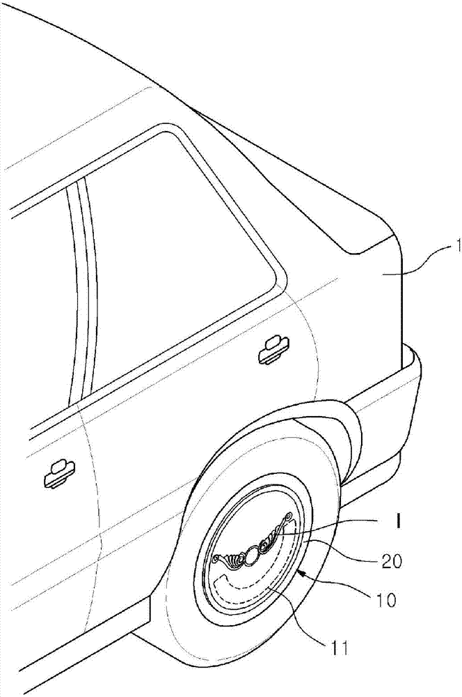
[0032] The rotating wheel 200 of the preferred embodiment of the present invention is installed on the lower part of the mobile device 1 to drive the mobile device 1 as it rotates and is equipped with an image board 100 that displays the image I in a stationary state regardless of the rotation of the rotating wheel 200. The rotating wheel 200 includes a wheel 210 and an image board 100 .

[0033] Wherein, the above-mentioned moving device 1 can travel by means of the rotating wheel 200, as a moving device provided with a wheel 210 on which the image board 100 can be installed on the above-mentioned rotating wheel 200, such as figure 1 , Image 6 and Figure 7As shown, the above-mentioned mobile ...


PUM


Abstract

According to the characteristics of the present invention, there is provided an image panel for a rotary wheel, that is, the image panel for a rotary wheel is attached to the rotary wheel (200) of the moving device (1) and displays a static image irrespective of the rotation of the rotary wheel (200). The image (I) of state, above-mentioned rotating wheel image plate comprises: substrate (110), and upright configuration is arranged on the outer side or the inner side of the wheel (210) that is arranged on above-mentioned rotating wheel (200), so that it can be positioned relative to the wheel (210) Installed in a manner to rotate independently, a prescribed image (I) is arranged on one side or both sides of the above-mentioned base plate (110); and the impeller (120), fastened to the lower part of the above-mentioned base plate (110), moves The running wind force flowing in from the running of the device (1) rotates in a direction opposite to that of the above-mentioned rotating wheel (200).

Description

technical field [0001] The present invention relates to an image plate for a rotating wheel and a rotating wheel including the same. More specifically, it relates to an image for a rotating wheel that is mounted on a moving device such as an automobile or a bicycle and displays a stationary image regardless of the rotation of the rotating wheel. Plate and its rotating wheels. Background technique [0002] exist Figure 1 to Figure 3 discloses the structure of a conventional image plate for a rotary wheel. [0003] refer to figure 1 and figure 2 In the state where the counterweight 11 having a predetermined load is attached to the lower part of the conventional rotating wheel image board 10, the above-mentioned conventional rotating wheel is installed on the side of the wheel 20 of the automobile 1 so as to be rotatable via a bearing (not shown). The image plate 10 for the rotating wheel is provided with various forms of design images I such as logos, badges or advertisi...

Claims


Application Information

Patent Timeline
Patent Type & Authority Patents(China)
IPC IPC(8): B60B7/01B60B7/04
CPCB60B7/0053B60B7/04B60B7/066B60B7/20B60B2200/22B60B2900/572B60Y2200/10B60B7/01
Inventor 柳忠燮金尹花金成勋
Owner MIRYOON W&T CORP
Why Eureka
Try Eureka