
Subscriber station for a bus system and method for time-optimized data transmission in a bus system

A bus system and user station technology, applied in the field of time-optimized data transmission, can solve the problem of not being able to increase the baud rate arbitrarily, and achieve the effect of improving the transmission speed of CAN

Active Publication Date: 2016-08-31
ROBERT BOSCH GMBH
View PDF6 Cites 6 Cited by
  • Summary
  • Abstract
  • Description
  • Claims
  • Application Information

AI Technical Summary

Problems solved by technology

[0008] Therefore, given the physical extent of the bus system or network, the baud rate cannot be increased arbitrarily during arbitration

Method used


Image

  • Subscriber station for a bus system and method for time-optimized data transmission in a bus system
  • Subscriber station for a bus system and method for time-optimized data transmission in a bus system
  • Subscriber station for a bus system and method for time-optimized data transmission in a bus system

Examples


Embodiment Construction

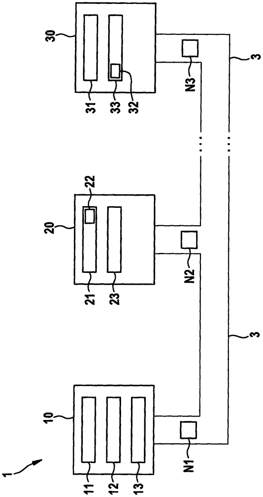
[0034] figure 1 A bus system 1 is shown, which can be, for example, a CAN bus system, a CAN FD bus system or the like. The bus system 1 can be used in vehicles, in particular motor vehicles, aircraft, etc., or in hospitals or the like.

[0035] exist figure 1 In this case, the bus system 1 has a bus line 3 to which a plurality of subscriber stations 10 , 20 , 30 are connected. Messages N1 , N2 , N3 in the form of signals can be transmitted between the individual subscriber stations 10 , 20 , 30 via the bus line 3 . Subscriber stations 10 , 20 , 30 can be, for example, control units, sensors, display devices, etc. of a motor vehicle.

[0036] Such as figure 1 As shown in , the subscriber station 10 has a communication control device 11 , an encoding device 12 and a transmitting / receiving device 13 . In contrast, the subscriber station 20 has a communication control device 21 , an encoding device 22 and a transmitting / receiving device 23 . The subscriber station 30 has a c...


PUM


Abstract

The invention relates to a subscriber station (20; 30; 200; 300) for a bus system (1) and a method for time-optimized data transmission in a bus system (1; 2). The subscriber station (20; 30; 200; 300) comprises coding means (12; 22; 32; 120; 220; 320) for encoding and / or decoding bits of a message (N1; N2; N3; (10, 20, 30; 100, 200, 300) to a bus line (3) of the at least one bus station (3) of the bus system (1); symmetrical information (N1; N2; N3; N4; N5; N6) enables at least two bits as a bit combination (N1; N2; N3; N4; N5; N6) to a predetermined voltage level for a bit time (TB), and / or wherein said encoding means (12; 22; 32; 120; To a predetermined voltage level for a bit time (TB) at least two bits as a bit combination.

Description

technical field [0001] The invention relates to a subscriber station for a bus system and to a method for time-optimized data transmission in a bus system. Background technique [0002] For communication between sensors and control devices, the CAN bus system has become widely popular, for example in automobiles. In the CAN bus system, messages are transmitted by means of the CAN protocol as described in ISO11898. In particular, automotive bus systems continue to develop higher bandwidth, shorter latency and stricter real-time performance. Techniques such as CAN FD have also recently been proposed for this purpose, in which the maximum data rate has been increased to values ​​above 1 MBit / s by using higher clocks in the area of ​​the data field. Such messages are also referred to below as CAN FD frames or CAN FD messages. In the case of CAN FD, expanding the effective data length from 8 bytes to 64 bytes, the data transmission rate is significantly higher than in the case...

Claims


Application Information

Patent Timeline
Patent Type & Authority Applications(China)
IPC IPC(8): H04L1/00H04L12/40
CPCH04L1/0006H04L12/4013H04L2012/40215G06F13/3625G06F13/372
Inventor S·蒂勒
Owner ROBERT BOSCH GMBH
Learn More