Optical path difference measurement method and device based on spatial optical path difference modulation

A measurement method and optical path difference technology, which are applied to measurement devices, use optical devices to transmit sensing components, convert sensor outputs, and other directions, and can solve problems such as inability to calculate data weights

Inactive Publication Date: 2018-07-10
NANJING INST OF ASTRONOMICAL OPTICS & TECH NAT ASTRONOMICAL OBSE
View PDF4 Cites 0 Cited by
  • Summary
  • Abstract
  • Description
  • Claims
  • Application Information

AI Technical Summary

Problems solved by technology

But Lawson pointed out that the spatial modulation method has the disadvantage of not being able to calculate the weight of the data obtained for each wavelength (for example, according to the signal-to-noise ratio)
In addition, the spatial modulation method can only measure the optical path difference modulo the average wavelength

Method used


Image

  • Optical path difference measurement method and device based on spatial optical path difference modulation
  • Optical path difference measurement method and device based on spatial optical path difference modulation
  • Optical path difference measurement method and device based on spatial optical path difference modulation

Examples


Embodiment 1

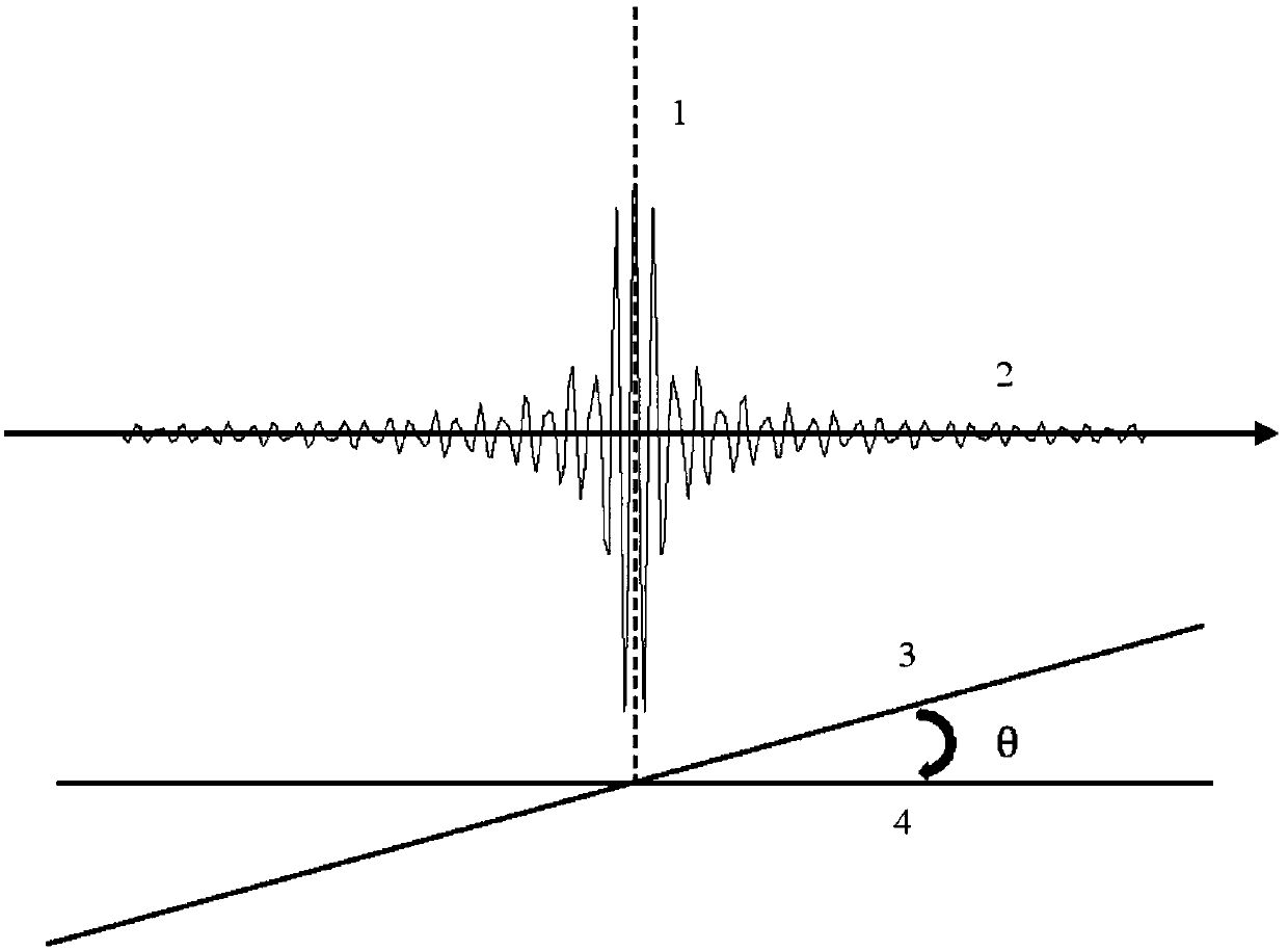
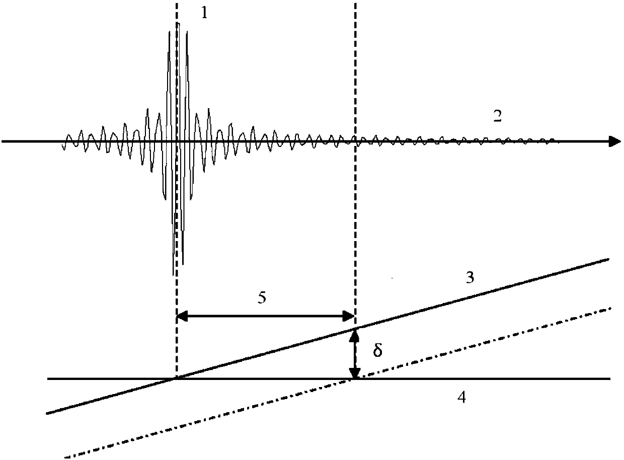
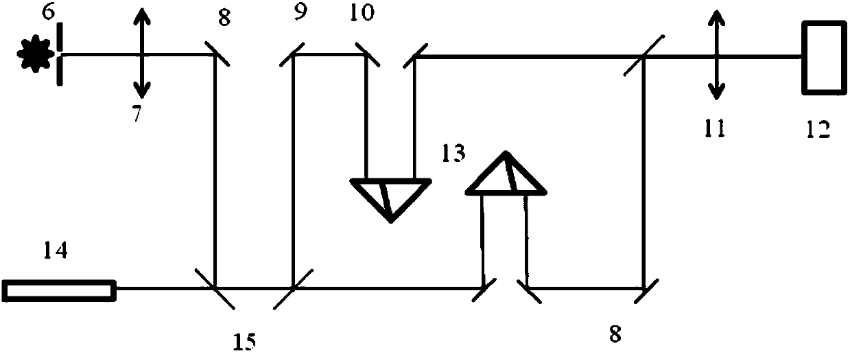
[0045] Embodiment 1, the implementation of the present invention includes: introducing a tilt between the two beams participating in the beam combination to produce static optical path difference modulation; using broadband white light to obtain white light interference fringes; using an algorithm to extract the position of the white light interference fringes, and using the fringe Position calculates the optical path difference between the two beams. The device diagram of embodiment 1 is as follows figure 2 shown.

[0046] Among the figure, broadband LED and 25 micron diameter small hole 6, collimator lens 7, plane mirror 8, second flat beam splitter 9, third flat beam splitter 10, imaging lens 11, CCD detector 12, corner cube 13 , laser 14 , first flat beam splitter 15 .

[0047] The device used in the optical path difference measurement method based on spatial optical path difference modulation adopts a broadband LED through a small circular hole as a light source; a col...


PUM


Abstract

The invention provides a light path difference measurement method based on space light path difference modulation and a device thereof. (1) a broadband LED through a small circular hole acts as a light source; (2) collimated light beams are formed through a collimating lens; (3) laser and white light are coupled by a first flat beam splitter; (4) the coupled light is split into two identical beams of light through a second flat beam splitter; (5) the two beams of light respectively passes through a reflecting mirror and a corner matched prism which are identical, and one corner matched prism is arranged on a high-precision linear motor translation table so as to provide high-precision light path difference control; (6) the two beams of light is combined through a third flat beam splitter, and a small inclination angle between the two beams of light is provided; (7) interference fringes formed by the two beams of light are imaged to a charge coupled device detector by an imaging lens; (8) the interference fringe position is extracted by using an algorithm; and (9) the light path difference between the two beams of light is calculated so that a measurement result is obtained. The method is not sensitive to atmospheric turbulence. The maximum error is 0.159 microns and is less than average wavelength so that the precision meets the requirements of fringe interference.

Description

technical field [0001] The invention belongs to the technical field of astronomical instruments, and in particular relates to an optical path difference measurement method based on spatial optical path difference modulation, and a device used in the measurement method. technical background [0002] Astronomical optical interferometry is a technology that connects no less than two telescopes / stationary mirrors by using delay lines and beam combiners to obtain high-resolution astronomical observation capabilities. Atmospheric perturbations cause a random optical path difference between beams from different telescopes / statiostats. The existence of random optical path difference makes the fringes formed by the two light beams jitter randomly. The random jitter of the fringes limits the integration time to 10 milliradians. The limitation of integration time reduces the observation sensitivity of astronomical optical interferometry technology and reduces the observable magnitude...

Claims


Application Information

Patent Timeline
Patent Type & Authority Patents(China)
IPC IPC(8): G01D5/28
CPCG01D5/285
Inventor 孙长胜朱永田胡中文徐腾
Owner NANJING INST OF ASTRONOMICAL OPTICS & TECH NAT ASTRONOMICAL OBSE
Why Eureka
Try Eureka