
A liquid bridge generator with rotatable upper liquid bridge column

A generator and rotary technology, applied in the field of fluid physics, can solve the problems of manual measurement, can not be used to study the influence of liquid bridge, and affect the accuracy of the experiment, so as to improve the accuracy, increase the accuracy of the experiment, and have a simple structure Effect

Active Publication Date: 2018-05-04
NORTHEASTERN UNIV LIAONING
View PDF7 Cites 0 Cited by
  • Summary
  • Abstract
  • Description
  • Claims
  • Application Information

AI Technical Summary

Problems solved by technology

However, this liquid bridge generator, like the traditional liquid bridge generator, still cannot be used to study the influence of dynamic changes inside the liquid bridge on its free surface
In addition, the liquid bridge height of the liquid bridge generator disclosed in Chinese patent CN204738041 needs to be manually measured, which will inevitably cause measurement errors and affect the accuracy of the experiment.

Method used


Image

  • A liquid bridge generator with rotatable upper liquid bridge column
  • A liquid bridge generator with rotatable upper liquid bridge column
  • A liquid bridge generator with rotatable upper liquid bridge column

Examples


Embodiment Construction

[0019] The present invention will be described in detail below in conjunction with the accompanying drawings, but the protection scope of the present invention is not limited to the following embodiments.

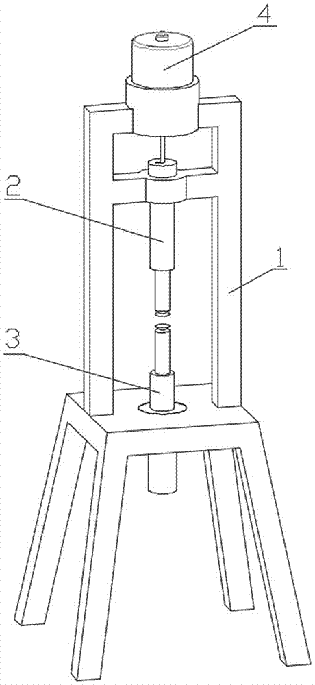
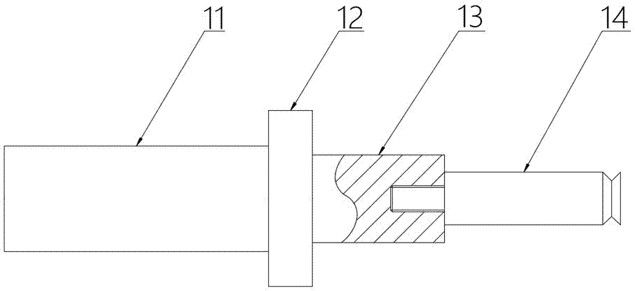
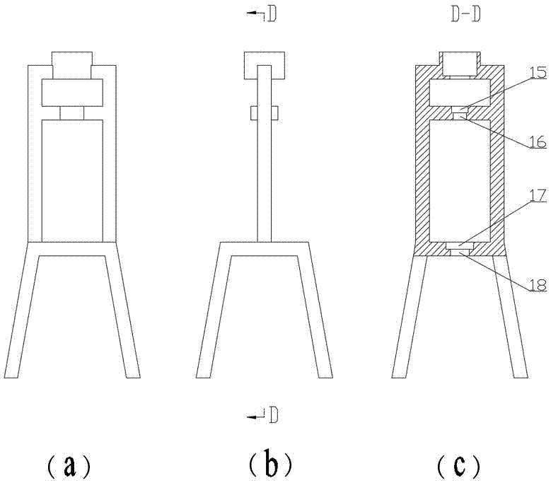
[0020] A liquid bridge generator with a rotatable upper liquid bridge column, such as figure 1 As shown, including bracket 1 (its structure is as Figure 4 As shown), the controllable speed motor 4 is installed on the upper part of the bracket, the upper liquid bridge column mounting hole 16 and the upper liquid bridge column clamping groove 15 are arranged on the bracket directly below the motor, the lower liquid bridge column mounting hole 18 and the lower The liquid bridge column clamping groove 17, the upper liquid bridge column 2 and the lower liquid bridge column 3 are installed vertically through the upper liquid bridge column mounting hole 16 and the lower liquid bridge column mounting hole 18 respectively and keep the center relative; the upper liquid bridge column...


PUM

PropertyMeasurementUnit
heightaaaaaaaaaa

Abstract

The invention provides an upper liquid bridge column rotatable liquid bridge generator, which includes a bracket. A motor is installed on the upper part of the bracket. The bracket directly below the motor is provided with an upper liquid bridge column mounting hole and an upper liquid bridge column slot. The lower part of the bracket is provided with an upper liquid bridge column mounting hole and an upper liquid bridge column slot. There is a lower liquid bridge column installation hole and a lower liquid bridge column slot. The upper liquid bridge column and the lower liquid bridge column are installed vertically through the upper liquid bridge column installation hole and the lower liquid bridge column installation hole respectively and keep the centers facing each other; the upper liquid bridge column The bridge column includes the upper liquid bridge column rod, the upper plate and the upper liquid bridge column snap ring with the same outer diameter as the upper liquid bridge column clamping groove. The upper liquid bridge column rod and the upper plate are connected through threads, and the upper liquid bridge column snap ring Welded on the upper liquid bridge column; the lower liquid bridge column includes the lower liquid bridge column upper rod, the lower liquid bridge column lower rod, the lower plate and the lower liquid bridge column with the same outer diameter and height as the lower liquid bridge column slot. The snap ring, the upper rod of the lower liquid bridge column and the lower plate are connected through threads, and the lower liquid bridge column snap ring is welded at the connection between the upper rod of the lower liquid bridge column and the lower rod of the lower liquid bridge column; the rotating shaft of the motor is connected to the upper Liquid bridge column rod connection.

Description

technical field [0001] The invention belongs to the technical field of fluid physics, in particular to a liquid bridge generator with a rotatable upper liquid bridge column. Background technique [0002] As a method of area purification for growing crystals, the floating zone method is mainly used for high-quality semiconductor crystal growth. Large-sized single crystals can also be obtained if the method is applied in a microgravity environment. Therefore, the floating zone method has become one of the most promising methods in the preparation of space materials. [0003] In existing research experiments, the physical model used to simulate the crystal growth process in the floating zone method is called a liquid bridge. The height-to-diameter ratio of the liquid bridge has an important influence on the internal flow and free surface of the liquid bridge, so we usually need to adjust the liquid bridge diameter of the liquid bridge generator according to the experimental s...

Claims


Application Information

Patent Timeline
Patent Type & Authority Patents(China)
IPC IPC(8): C30B13/00
CPCC30B13/00
Inventor 梁儒全李湛王奎阳赵俊楠张硕李晓媛朱林阳杨硕
Owner NORTHEASTERN UNIV LIAONING
Learn More