Eureka AIR delivers breakthrough ideas for toughest innovation challenges, trusted by R&D personnel around the world.

An automatic tire dewatering machine

An automatic tire and nozzle technology, which is applied in metal processing and other directions, can solve the problems of slow cutting operation speed, uneven nozzle cutting, rough manual operation, etc., to facilitate later assembly, improve accuracy, strengthen accuracy and stability Effect

Active Publication Date: 2019-04-02
DONGGUAN SUMS MODEL GIFTS CO LTD
View PDF3 Cites 0 Cited by
  • Summary
  • Abstract
  • Description
  • Claims
  • Application Information

AI Technical Summary

Problems solved by technology

[0003] At present, there are many ways to remove the nozzle, and a simple nozzle-cutting jig is used for manual cutting operation, that is, after injection molding, the molded plastic tire product is manually taken and put into a simple nozzle-cutting fixture to cut and remove the nozzle. Then pick up the plastic products from the nozzle fixture and put them into the next process, which makes the cutting operation slow and inefficient. Due to the rough manual operation, the nozzle cutting is not smooth

Method used


Image

  • An automatic tire dewatering machine
  • An automatic tire dewatering machine
  • An automatic tire dewatering machine

Examples


Embodiment Construction

[0021] In order to enable the review committee to have a further understanding of the purpose, features and functions of the present invention, the preferred embodiments are hereby given in detail in conjunction with the drawings as follows:

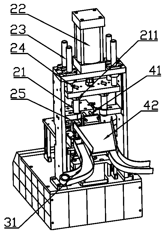
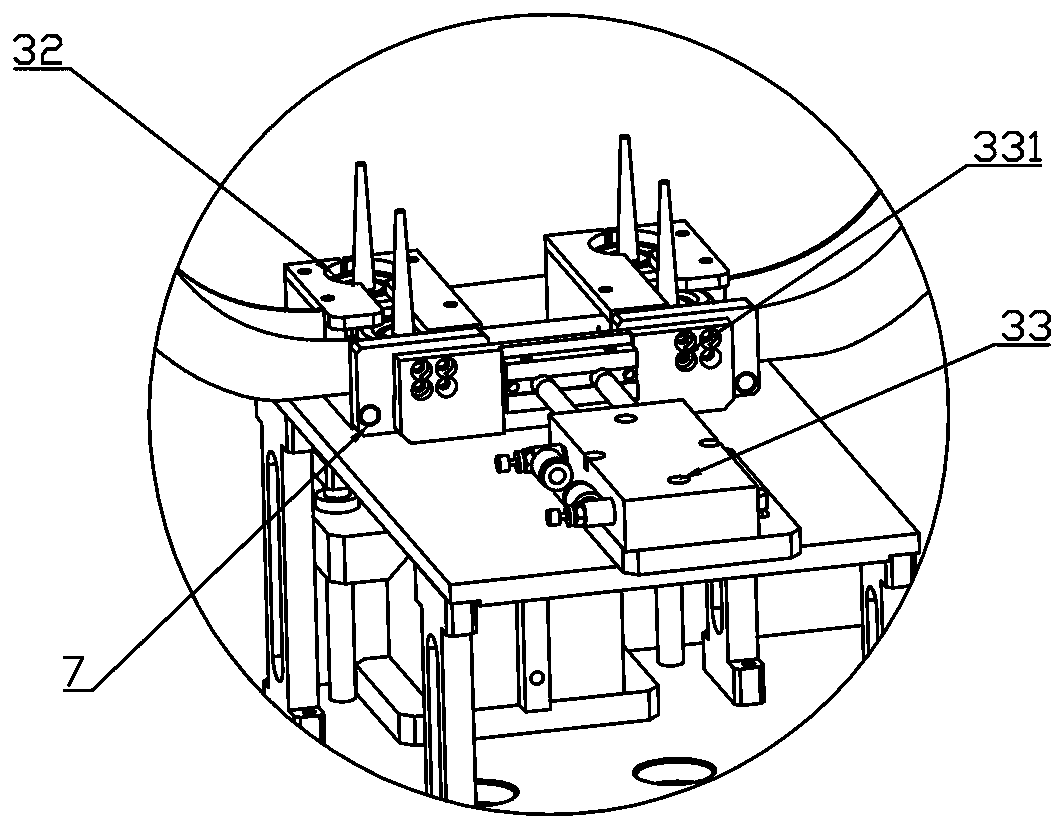
[0022] Figure 1~4 As shown, it is a structural schematic diagram of a preferred embodiment of the present invention. The present invention is an automatic tire dewatering machine, which mainly includes: a vibrating conveying unit 1, a stamping unit 2, a positioning unit 3 and an unloading unit 4. The vibrating conveying unit 1 is located on both sides of the workbench 5, the vibrating conveying unit 1 is connected to the positioning part 32 of the positioning unit 3 through the rail 6, the stamping unit 2 is located above the positioning unit 3, and the unloading unit 4 is located between the stamping unit 2 and the positioning unit Between 3, the cutting knife 21 is stamped to the positioning unit 3 by pressing down the cylinder 22, an...


PUM


Abstract

The invention relates to the field of toy mechanical equipment, in particular to an automatic tire drainage opening cutting machine. The automatic tire drainage opening cutting machine mainly comprises vibration conveying units, a stamping unit, a positioning unit and a discharging unit. The vibration conveying units are located on the two sides of a workbench and connected to positioning parts of the positioning unit through tracks. The stamping unit is located over the positioning unit. The discharging unit is located between the stamping unit and the positioning unit. Cutters are stamped to the positioning unit through a downward pressing air cylinder. A controller is arranged under the workbench. The automatic tire drainage opening cutting machine has the beneficial effects that the drainage opening cutting mechanism cuts tire drainage openings through the cutters of the stamping unit, and the cutters adsorb cut drainage opening waste materials to the discharging unit; and compared with traditional manual drainage opening cutting, not only is the product production efficiency improved by the design, but also the manufacturing cost and manpower are greatly reduced.

Description

technical field [0001] The invention relates to the field of toy machinery equipment, in particular to an automatic tire drain machine. Background technique [0002] Common plastic tire products in daily life are usually molded by injection molding, and plastic tire products are used for toy car models. During processing and molding, there will be nozzles left on the plastic tire product. The so-called nozzle refers to the excess material left on the plastic tire product during injection molding. [0003] At present, there are many ways to remove the nozzle, and a simple nozzle-cutting jig is used for manual cutting operation, that is, after injection molding, the molded plastic tire product is manually taken and put into a simple nozzle-cutting fixture to cut and remove the nozzle. Then pick up the plastic products from the nozzle jig and put them into the next process, which makes the cutting operation slow and inefficient. Due to the rough manual operation, the nozzle cu...

Claims


Application Information

Patent Timeline
Patent Type & Authority Patents(China)
IPC IPC(8): B29C45/38B26D1/08B26D7/06B26D7/18B26D5/12B26D7/01
CPCB26D1/08B26D5/12B26D7/01B26D7/0641B26D7/1863B29C45/382
Inventor 刘学深
Owner DONGGUAN SUMS MODEL GIFTS CO LTD
Why Eureka
Eureka Blog
Learn More