Eureka AIR delivers breakthrough ideas for toughest innovation challenges, trusted by R&D personnel around the world.

Real-time dynamic focusing wave beam forming method and system

A focused beam, real-time dynamic technology, applied in the field of multi-beam bathymetry, can solve the problems of loss of measurement accuracy, inability to use shallow water multi-beam bathymetry for fast measurement, large dynamic beam focusing error, etc. Effect problem, effect of wide application

Inactive Publication Date: 2016-08-24
BEIJING HYDRO TECH MARINE TECH CO LTD
View PDF1 Cites 10 Cited by
  • Summary
  • Abstract
  • Description
  • Claims
  • Application Information

AI Technical Summary

Problems solved by technology

Among them, theoretical simulation is limited to the analysis of depth sounding accuracy, and cannot be applied to the rapid measurement of shallow water multi-beam echo sounder; although the segmented focusing method can be realized quickly, it is at the cost of loss of measurement accuracy
In their published article, Chen Ying et al proposed "A Fast Acoustic Imaging Algorithm Using Hierarchical Focusing Beamforming" (Chen Ying, Ye Qinghua, Huang Haining, Fast Acoustic Imaging Algorithm Using Hierarchical Focusing Beamforming[J], Applied Acoustics, 2008 , 27(3):207-210), although the calculation speed is improved, but the dynamic beam focusing error is large

Method used

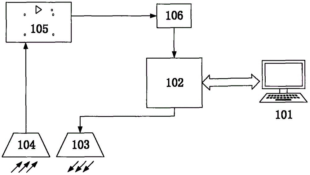
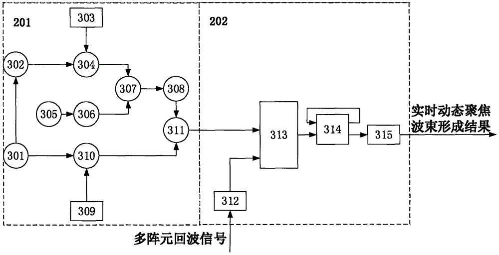

Image

  • Real-time dynamic focusing wave beam forming method and system
  • Real-time dynamic focusing wave beam forming method and system
  • Real-time dynamic focusing wave beam forming method and system

Examples


Embodiment Construction

[0026] specific implementation plan

[0027] The present invention will be further described below in conjunction with the accompanying drawings and a preferred specific embodiment of the present invention.

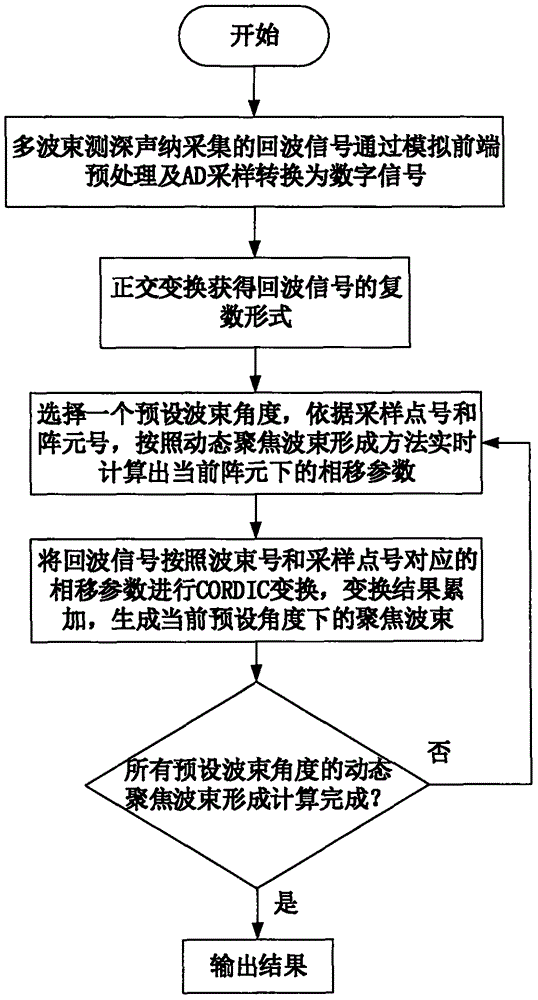
[0028] 1. A real-time dynamic focusing beamforming method implemented in this embodiment, such as figure 1 shown, including the following steps:

[0029] Step 1: Multi-beam sounding sonar collects echo signals, which are converted into digital signals through analog front-end preprocessing and analog-to-digital converters;

[0030] Step 2: The digital signal undergoes orthogonal transformation to obtain the complex form V of the echo signal m ;

[0031] Step 3: According to the preset beam angle θ of beamforming k , sampling point number n and array element number m, calculate the phase shift parameter τ of the current array element in real time according to the dynamic focusing beamforming method mk ;

[0032] Step Four: V m The phase shift parameter τ correspondi...


PUM


Abstract

The invention discloses a real-time dynamic focusing wave beam forming method and system. The method specifically comprises the following steps: echo sound signals are pre-processed by an analog front end and are processed by an analog-to-digital converter so as to be converted into digital signals; the digital signals are subjected to orthogonal transformation, and the plural form Vm of echo signals is obtained; according to a preset angle theta k, a sampling point number n and an array element number m formed by wave beams, calculating a phase shift parameter tau mk of a current array element in real time according to a dynamic focusing wave beam forming method; Vm rotates by the corresponding phase shift parameter tau mk, V'm is obtained, and each channel result is accumulated so as to obtain a real-time dynamic focusing wave beam forming result V(theta k) in a theta k direction; according to an equiangular or equidistance mode, presetting a wave beam angle theta k, repeating the above steps, and completing real-time dynamic focusing wave beam formation. According to the real-time dynamic focusing wave beam forming method and system, the dynamic focusing wave beam formation precision is not lost, the quick calculation capability is achieved, the structure is simple, the method and the system are easy to achieve, and a near field efficiency problem can be greatly solved; and the real-time dynamic focusing wave beam forming method and system can be widely applied to the multiple-wave-beam depth-sounding sonar shallow water depth-sounding field.

Description

technical field [0001] The invention belongs to the field of multi-beam sounding, and in particular relates to a real-time dynamic focusing beam forming method and system capable of solving the near-field effect and having high measurement accuracy. Background technique [0002] my country has a large area of ​​sea area and rivers, lakes and inland rivers, and most of them belong to shallow water environment. In order to fully understand the underwater topography, shallow water multi-beam echo sounders play an irreplaceable role. With the continuous advancement of science and technology, people have higher and higher requirements for the accuracy of underwater terrain acquisition. In order to simplify calculations in conventional multi-beam echo sounders, far-field approximate models are often used. When r>>D 2 High accuracy can be guaranteed when / λ, where r is the distance from the target to the center of the array element, D is the aperture size of the base array, a...

Claims


Application Information

Patent Timeline
IPC IPC(8): G01S15/08G01S7/539G01C13/00
CPCG01S15/08G01C13/008G01S7/539
Inventor 鲁东汤云龙吴霖真王尔迅金旗林
Owner BEIJING HYDRO TECH MARINE TECH CO LTD
Why Eureka
Eureka Blog
Learn More