Eureka AIR delivers breakthrough ideas for toughest innovation challenges, trusted by R&D personnel around the world.

A hand-push conveying device applied to a construction site

A technology for construction sites and transportation devices, which is applied to trolleys, single-axis trolleys, trolley accessories, etc., and can solve problems such as potential safety hazards, cart rollovers, and impact on unloading

Active Publication Date: 2017-11-21
CHINA MCC5 GROUP CORP
View PDF8 Cites 0 Cited by
  • Summary
  • Abstract
  • Description
  • Claims
  • Application Information

AI Technical Summary

Problems solved by technology

[0006] The purpose of the present invention is to provide a hand-push conveying device applied to a construction site, so as to solve the problem that the current wheelbarrow needs to load and unload goods on a slope, the operation efficiency is not high, and it is easy to cause the cart to run out of control, with a In addition, in the process of unloading, it is not only laborious and inconvenient, but also easily causes the cart to overturn, affects the unloading, and even causes the operator to be injured. It also solves the problem that the transport trolley on the construction site cannot Adapting to the complex terrain, the cart is prone to tipping over during the delivery of goods, causing the goods to scatter, and even causing injury to the cart personnel

Method used


Image

  • A hand-push conveying device applied to a construction site
  • A hand-push conveying device applied to a construction site
  • A hand-push conveying device applied to a construction site

Examples


Embodiment 1

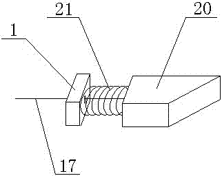
[0054] Such as Figure 1~Figure 13 As shown, a hand-push conveying device applied to a construction site described in this embodiment includes a car board 1, a car bucket 2, a single wheel 3 and a handlebar 6, and the car bucket 2 is located above the car board 1. The wheel 3 is fixed below the vehicle board 1 through the wheel board 4, the handlebar 6 is fixed on the vehicle board 1, and also includes an insertion device, a sliding device and a locking device, the insertion device is fixed on the vehicle board 1 or the handlebar 6, The sliding device is used to realize the back and forth movement of the vehicle bucket 2 on the vehicle panel 1, and the locking device is used to fix the vehicle bucket 2.

[0055] The insertion device of the present embodiment comprises a connecting rod 5, a flat plate 8 and an insertion socket 9 arranged below the flat plate 8, one end of the connecting rod 5 is fixed on the vehicle plate 1 or the handlebar 6, and the other end is fixed on the ...

Embodiment 2

[0069] Such as Figure 14 As shown, on the basis of Embodiment 1, this embodiment adds an auxiliary plate 25 and several fourth springs 26, the auxiliary plate 25 is hinged with the end of the vehicle plate 1 away from the handlebar 6, and one end of the fourth spring 26 is fixed on the auxiliary Below the plate 25, the other end is fixed on the car plate 1.

[0070] In addition, the present embodiment also includes several fifth springs 27 , one end of the fifth spring 27 is fixed on the bottom of the bucket 2 , and the other end is fixed on the auxiliary plate 25 .

[0071] The present embodiment adopts the above-mentioned structure to solve the following problems:

[0072] 1. Solve the balance problem when the cart is parked on a slope. Traditional trolleys are docked in a point-to-point manner. When the support rod as a docking support point is inserted into the soil, since the center of gravity of the goods on the trolley is not necessarily just at the center of the tro...


PUM


Abstract

The invention discloses a hand-push type delivery device applied to construction sites. The hand-push type delivery device comprises a vehicle board, a hopper, a single wheel, a handlebar, an inserting unit, a sliding unit and a locking unit, the hopper is located above the vehicle board, the single wheel is fixed under the vehicle board, the handlebar is fixed on the vehicle board, the locking unit is used for fixing the hopper, the inserting unit is fixed on the vehicle board or the handlebar, the sliding unit is used for driving the hopper to move back and forth on the vehicle board, the sliding unit comprises guiding slide grooves arranged in the vehicle board and guiding wheels arranged at the bottom of the hopper, and the guiding wheels are matched with the guiding slide grooves; the hand-push type delivery device further comprises tilting prevention units arranged on two sides of the vehicle board, and the tilting prevention units can be opened downwardly and retracted to the direction of the bottom of the vehicle board. By the aid of the above structure, the hand-push type delivery device can be reliably pulled off on slopes, the hand-push type delivery device is labor saving in unloading and adaptable to different terrains, and the vehicle can be avoided toppling over.

Description

technical field [0001] The invention relates to the field of building construction, in particular to a hand-push conveying device applied to a construction site. Background technique [0002] In building construction, due to the construction environment and terrain, generally large and fast transfer equipment cannot be used. At this time, trolleys have become an indispensable means of transportation in the construction process, especially wheelbarrows. It only needs one wheel to touch the ground, and it is more adaptable to the building construction terrain, so it has been widely used. [0003] At present, when the wheelbarrow is parked, the handle is directly put down, so that the support rod and the wheel are used as a triangular support, so that the cart and the objects on the cart are stopped. On construction sites, especially outdoor construction sites, it is often encountered that the place where goods need to be loaded and unloaded is not flat, but on a slope. At thi...

Claims


Application Information

Patent Timeline
Patent Type & Authority Patents(China)
IPC IPC(8): B62B1/12B62B1/16B62B5/00
CPCB62B1/008B62B1/12B62B1/16B62B5/00B62B5/0003B62B5/0006B62B2203/07
Inventor 文常娟刘龙平
Owner CHINA MCC5 GROUP CORP
Why Eureka
Eureka Blog
Learn More