
Valve stem and plug connections and staking tools

A technology for riveting tools and valve stems, applied in the direction of manufacturing tools, connecting components, shrinking connections, etc., and can solve problems such as loosening, misalignment of valve stem and valve plug connection, and valve stem wear.

Active Publication Date: 2016-08-24
FISHER CONTROLS INT LLC
View PDF7 Cites 3 Cited by
  • Summary
  • Abstract
  • Description
  • Claims
  • Application Information

AI Technical Summary

Problems solved by technology

Additionally, when known valves are exposed to high temperatures and / or high vibrations, the valve stem can become worn and loosen within the opening of the valve plug
As a result, the stem and plug connections become misaligned and, as a result, maintenance or replacement is required

Method used


Image

  • Valve stem and plug connections and staking tools
  • Valve stem and plug connections and staking tools
  • Valve stem and plug connections and staking tools

Examples


Embodiment Construction

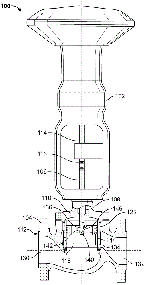
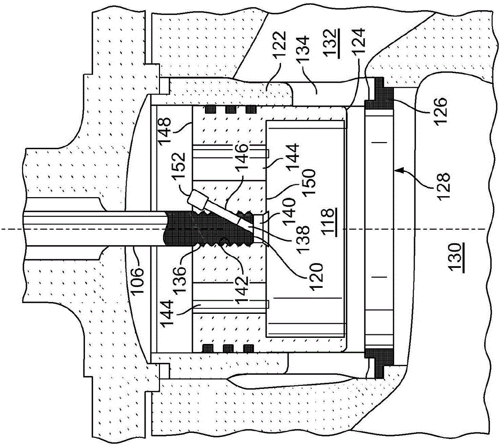
[0026] Before describing the details of the exemplary stem and plug connections and exemplary riveting tools disclosed herein, a brief discussion of known sliding stem valves is first provided in conjunction with FIGS. 1 , 2 and 3 . FIG. 1 is a partially cutaway schematic illustration of a known pneumatically actuated sliding stem valve 100 . Actuator 102 is coupled to valve body 104 and controls movement of stem 106 . Stem 106 extends through priming system 108 of bonnet 110 and into valve assembly 112 . FIG. 2 is an enlarged illustration of a portion of valve assembly 112 of FIG. 1 , including stem 106 . The valve stem 106 is coupled to the actuator rod 114 at an upper end 116 of the valve stem 106 and is coupled to a valve plug 118 at a lower end 120 of the valve stem 106 . Valve plug 118 is movable within cage 122 and includes bearing surface 124 that cooperates with valve seat 126 of orifice 128 to control the port area through which fluid may flow from inlet passage 13...


PUM


Abstract

Example valve stem and plug connections and example staking tools are described herein. An example apparatus includes a valve plug having a first side, a second side opposite the first side and a bore extending from the first side to the second side. A first portion of the bore is tapered from a first diameter to a second diameter smaller than the first diameter. A valve stem is disposed within the bore of the valve plug. The valve stem includes a first section, a second section and a third section between the first and second sections. The third section is tapered from a third diameter to a fourth diameter smaller than the third diameter. The tapers of the first portion of the valve plug and the third section of the valve stem, when engaged, create a frictional force that resists movement of the valve stem out of the bore.

Description

technical field [0001] The present disclosure relates generally to valves and, more particularly, to valve stem and plug connections and riveting tools. Background technique [0002] Control valves are commonly used in process control systems, such as, for example, for controlling product flow in food processing plants, for maintaining liquid levels in large tank farms, and the like. Control valves are used to manage product flow or maintain liquid levels by acting as variable passages. The amount of fluid flowing through the valve body of the control valve can be accurately controlled by precise movement of a valve plug (eg, valve member) disposed within the valve body. In some known automatic control valves, such as sliding stem valves (e.g., gate valves, globe valves, diaphragm valves, pinch valves, etc.), a valve stem operably couples the valve plug to the actuator . An actuator moves a valve plug within the valve body relative to a seat ring between an open position ...

Claims


Application Information

Patent Timeline
IPC IPC(8): B21J15/14F16K1/48
CPCB21J15/14F16K1/487F16B4/004F16K1/36F16K1/48B25B27/24F16B39/025F16B39/04F16B41/002B23P19/04B21J15/48B23P15/001F16K31/508
Inventor P·T·奥尔曼
Owner FISHER CONTROLS INT LLC
Learn More