a traction transformer

A traction transformer and winding technology, applied in the direction of transformers, fixed transformers, transformer/inductor coils/windings/connections, etc., can solve problems such as voltage, current and power conversion, and achieve simplified winding structure, easy implementation, economical and practical Effect

Active Publication Date: 2018-04-24
SOUTHWEST JIAOTONG UNIV
View PDF4 Cites 0 Cited by
  • Summary
  • Abstract
  • Description
  • Claims
  • Application Information

AI Technical Summary

Problems solved by technology

[0004] The purpose of the present invention is to provide a traction transformer, which can effectively solve the problem of voltage, current and power conversion of the same transformer for traction power supply and power lighting power supply

Method used


Image

  • a traction transformer
  • a traction transformer

Examples


Embodiment

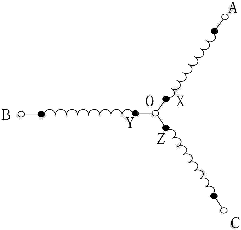
[0015] figure 1 It shows a primary side wiring diagram of a traction transformer. The three-phase windings on the primary side are star-connected, that is, the tail ends X, Y, and Z of the three-phase windings AX, BY, and CZ on the primary side are connected to form a midpoint 0, The first ends A, B, and C of the three-phase windings AX, BY, and CZ on the primary side are connected to the three-phase power grid.

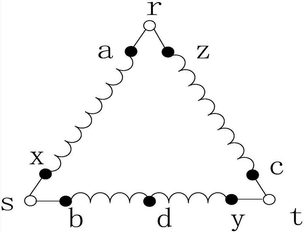
[0016] figure 2 Shown in the wiring diagram of the secondary side of the present invention, the three-phase windings ax, by, and cz of the secondary side are connected in a △ shape, that is, the first end a of the winding ax is connected to the tail end z of the winding cz to form a terminal r, and the first end b of the winding by is connected Terminal s is formed to the tail end x of the winding ax, the first end c of the winding cz is connected to the tail end y of the winding by to form a terminal t; the terminals r, s, t form a three-phase symmetrical connecti...


PUM


Abstract

The invention discloses a traction transformer, which belongs to the technical field of rail transit power supply and transformation. The three-phase windings on the primary side are star-connected, the first ends A, B, and C of the three-phase windings AX, BY, and CZ on the primary side are connected to the three-phase power grid; the three-phase windings ax, by, and cz on the secondary side are connected in a △ shape, that is The first end a of the winding ax is connected to the tail end z of the winding cz to form a terminal r, the head end b of the winding by is connected to the tail end x of the winding ax to form a terminal s, the first end c of the winding cz is connected to the tail end y of the winding by to form a terminal t; the terminal r , s, and t form a three-phase symmetrical connection; pull out terminal d at the midpoint of the secondary winding by, terminal r and terminal d form port rd, and port rd and port st form a two-phase symmetrical connection; three-phase symmetrical connection is used for power lighting Power supply; two-phase symmetrical wiring is used for traction power supply, which can be three-phase--two-phase balanced power supply mode, or the same-phase power supply mode. It is mainly used for traction power supply and power lighting power supply of rail transit.

Description

technical field [0001] The invention relates to the technical field of rail transit power supply and transformation, in particular to a transformer connection technology for traction loads and electric loads. Background technique [0002] Mainline electrified railways and urban rail transit such as subways and light rails all need traction power supply and power lighting power supply. Electrified railways often separate traction power supply and power lighting power supply to form two systems. The traction power supply system uses a single-phase power supply system, and the traction transformer in the traction substation adopts YNd11, Vv, three-phase-two-phase balance and other wiring forms. In the three-phase system for power lighting, the transformers in the substations mostly use the Dy connection method. The traction power supply and power lighting power supply of urban rail transit often share a three-phase 35kV medium voltage system, which is rectified into DC by the ...

Claims


Application Information

Patent Timeline
Patent Type & Authority Patents(China)
IPC IPC(8): H01F30/12H01F27/29H01F27/28
CPCH01F27/28H01F27/29H01F30/12
Inventor 李群湛解绍锋郭锴
Owner SOUTHWEST JIAOTONG UNIV
Why Eureka
Try Eureka