Sliding windows and how they work

A technology for sliding windows and inner windows, applied in door/window accessories, sealing devices, buildings, etc., which can solve the problem of moving the movable window to any position on the guide rail, limiting the movable range of the movable window, and changing the gap between the chute and the lock pin. Large and other problems, to achieve the effect of reducing occupancy, prolonging life, and saving effort during opening and closing

Active Publication Date: 2018-07-31
JIANGSU CHANG NING ET LTD
View PDF6 Cites 0 Cited by
  • Summary
  • Abstract
  • Description
  • Claims
  • Application Information

AI Technical Summary

Problems solved by technology

[0002] Sliding windows in the prior art, such as the flush sliding window described in the Chinese patent document with the document number CN202899905U and the flush sliding window for vehicles described in the Chinese patent document with the document number CN103790486A, two kinds of sliding windows After the window is closed, the movable window is flush with the outer surface of the fixed window. However, when the movable window is opened, the movable window can only be positioned by the square teeth or saw teeth set on the guide rail during the movement along the guide rail. , since each square tooth or saw-shaped tooth has a certain length, the movable window cannot be moved to any position on the guide rail in actual conditions, which limits the movable range of the movable window; The opening and closing structure of the window adopts S-shaped chute and lock pin. Under the action of thrust, the two slide relative to each other to open and close the movable window. The S-shaped chute and lock pin slide under the action of pressing force and are easy to wear. The gap between the chute and the lock pin becomes larger, and eventually the movable window cannot be opened and closed

Method used


Image

  • Sliding windows and how they work
  • Sliding windows and how they work
  • Sliding windows and how they work

Examples


Embodiment Construction

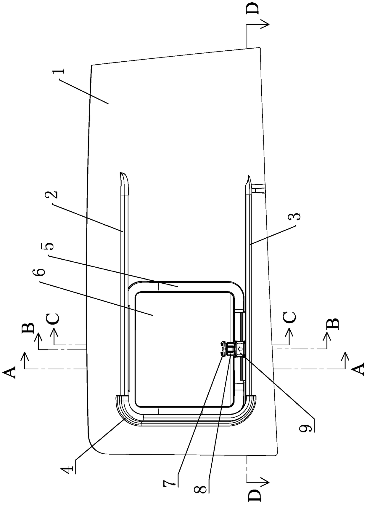
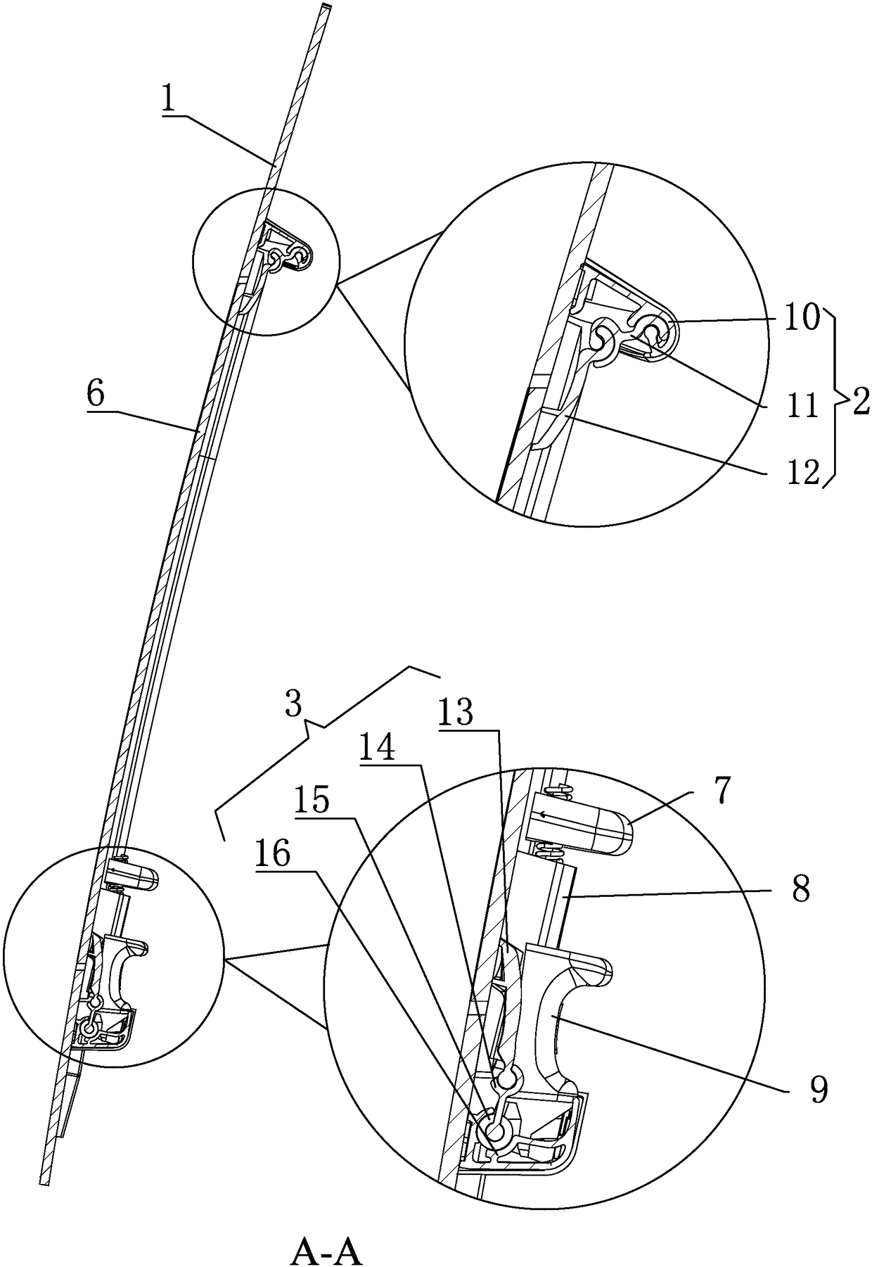
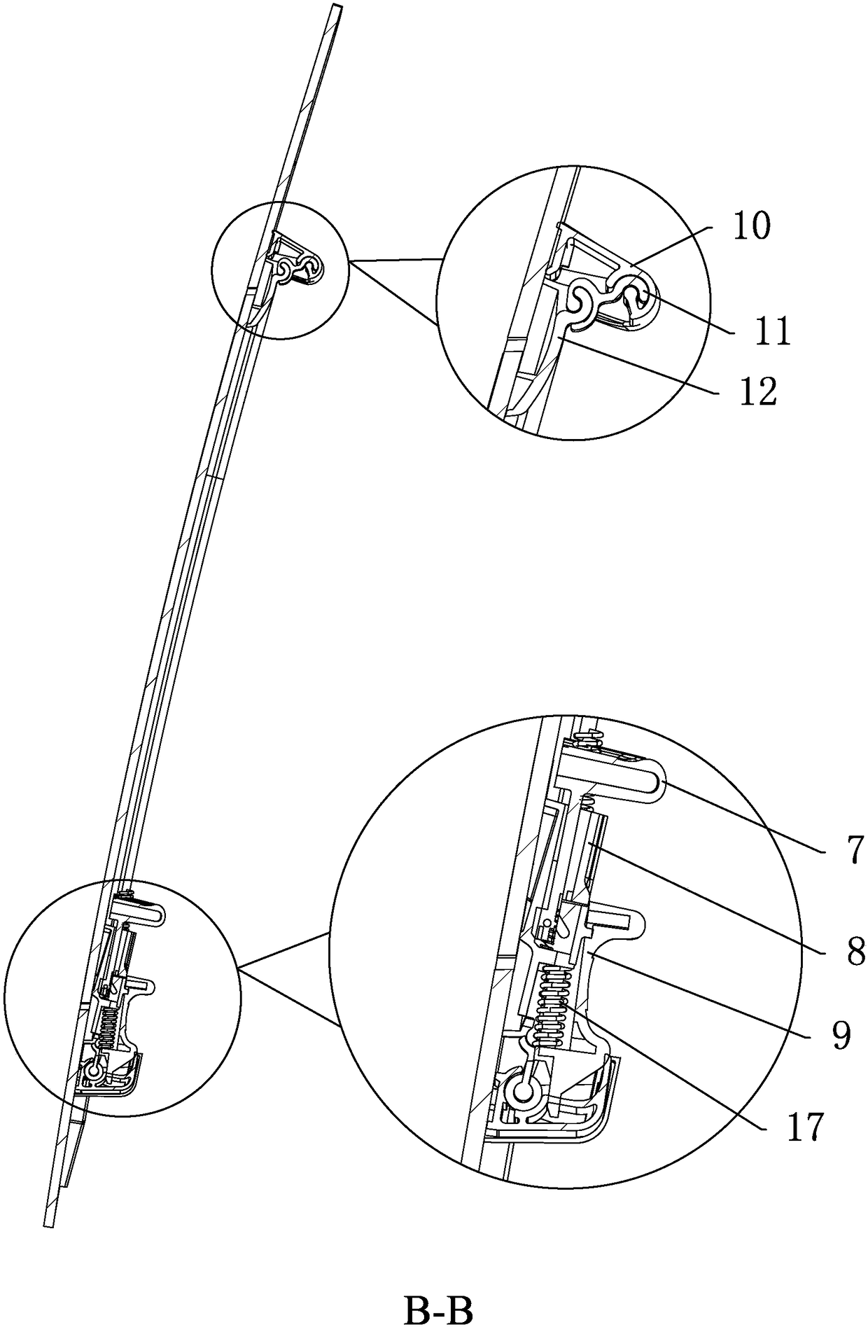
[0044] The sliding window includes: fixed window 1, upper sliding mechanism 2, lower sliding mechanism 3, window cover 4, inner window frame 5, inner window 6, upper handle 7, connecting block 8, lower handle 9, upper guide rail 10, upper connecting bar 11, upper bracket 12, lower bracket 13, lower connecting bar 14, casing 15, lower guide rail 16, spring 17, window hole 18.

[0045] Such as figure 1 and Figure 15As shown, the fixed window 1 is a glass structure, and the inner surface of the fixed window 1 is provided with a pair of horizontal sliding mechanisms, which include an upper sliding mechanism 2 and a lower sliding mechanism 3, and a fixed window 1 located between the upper and lower sliding mechanisms is provided. There is a window hole 18, the inner window 6 matches the shape of the window hole 18, the inner window 6 is made of glass, the outer circumference of the inner window 6 is provided with an inner window frame 5, and a seal is provided between the inner w...


PUM


Abstract

The invention relates to a sliding window and a working method thereof, which comprises: a sliding mechanism comprising an upper sliding mechanism, and a window hole matching with an inner window is opened on a fixed window under the upper sliding mechanism; the upper sliding mechanism comprises an upper guide rail, an upper guide rail Fixed on the inner side of the fixed window, the upper side of the upper connecting bar slides and fits with the upper guide rail along the length direction of the upper guide rail, the lower side of the upper connecting bar is hinged with the upper side of the upper bracket, and the lower side of the upper bracket and The inner surface of the inner window is fixedly connected; the inner window is suitable for opening and closing the window hole through the relative rotation of the upper connecting bar and the upper bracket, and the inner window is suitable for sliding relative to the upper guide rail through the upper connecting bar; the inner window of the sliding window passes through the upper The connecting bar and the hinge of the upper bracket realize the rotary opening and closing, and the upper connecting bar and the upper guide rail move along the length direction of the upper guide rail and can stay at any position between the extreme positions of the two sides.

Description

technical field [0001] The invention relates to a sliding window and a working method thereof, which are used for glass windows of vehicles or glass curtain walls. Background technique [0002] Sliding windows in the prior art, such as the flush sliding window described in the Chinese patent document with the document number CN202899905U and the flush sliding window for vehicles described in the Chinese patent document with the document number CN103790486A, two kinds of sliding windows After the window is closed, the movable window is flush with the outer surface of the fixed window. However, when the movable window is opened, the movable window can only be positioned by the square teeth or saw teeth set on the guide rail during the movement along the guide rail. , since each square tooth or saw-shaped tooth has a certain length, the movable window cannot be moved to any position on the guide rail in actual conditions, which limits the movable range of the movable window; T...

Claims


Application Information

Patent Timeline
Patent Type & Authority Patents(China)
IPC IPC(8): E06B3/46E06B7/16E05D13/00
Inventor 李德云
Owner JIANGSU CHANG NING ET LTD
Why Eureka
Try Eureka