
A igbt parallel static current sharing circuit

A static current sharing and circuit technology, applied in the direction of electrical components, output power conversion devices, etc., can solve the problem that the current level of a single IGBT cannot meet the requirements of the equipment, the static current of the parallel switch tubes is unbalanced, and the overall damage of the switch tubes and other issues to achieve mass production, improve accuracy and reliability, and prolong life

Active Publication Date: 2018-07-17
XI AN JIAOTONG UNIV
View PDF5 Cites 0 Cited by
  • Summary
  • Abstract
  • Description
  • Claims
  • Application Information

AI Technical Summary

Problems solved by technology

However, for high-voltage and high-power power electronic equipment, the current level of a single IGBT cannot meet the requirements of the equipment, which makes it an effective choice to connect multiple IGBTs in parallel as a basic unit
[0003] In the parallel application of IGBT, the inconsistency of the parameters of each IGBT may cause the inconsistency of the equivalent resistance of each parallel IGBT branch, which will lead to the unbalanced quiescent current of each parallel switch tube
Some IGBTs work at a high current for a long time, which will generate excessive heat accumulation, which will eventually lead to device damage, and the damage of some switch tubes will further lead to the overall damage of the remaining switch tubes

Method used


Image

  • A igbt parallel static current sharing circuit
  • A igbt parallel static current sharing circuit
  • A igbt parallel static current sharing circuit

Examples


Embodiment Construction

[0023] The present invention will be further described in detail below in conjunction with specific embodiments, which are explanations of the present invention rather than limitations.

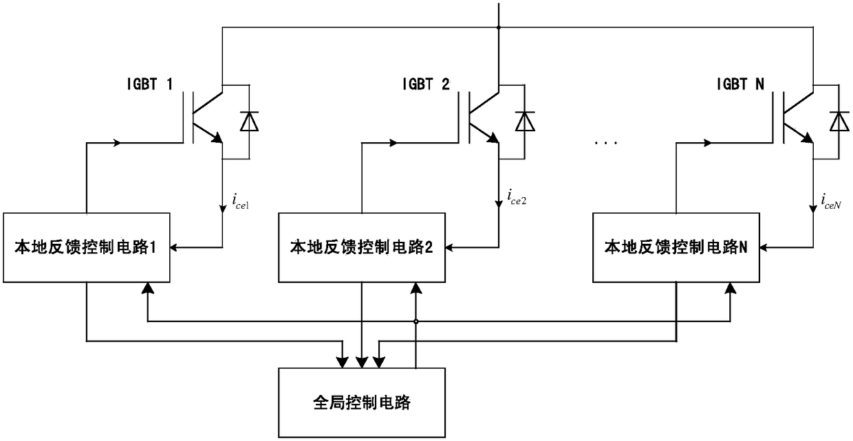
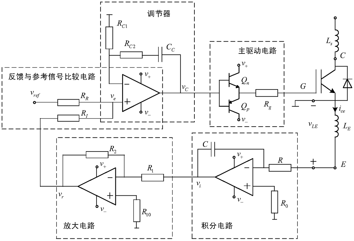
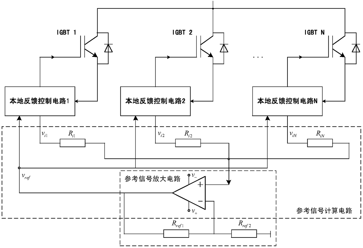
[0024] The IGBT collector current is determined by the collector-emitter saturation voltage drop and the gate voltage, so the IGBT collector current can be regulated by controlling the gate voltage. The present invention adopts the collector current closed-loop feedback control method, collects the calculated average value of each branch current as a reference signal, and regulates the collector current by adjusting the gate voltage value, thereby realizing the purpose of IGBT parallel static current sharing. The invention has simple structure and devices, is easy to realize, saves manual operation, can be produced in batches, and has good economical efficiency. In addition, the current equalizing circuit adopted in the present invention does not need to add a buffer circuit, so the switching...


PUM


Abstract

The invention provides an IGBT parallel static current sharing circuit which has advantages of static current sharing, accurate and reliable current sharing adjustment, stable switching frequency, long service life, and high suitability for power electronic equipment which requires IGBT parallel connection and is on for a long time period. The IGBT parallel static current sharing circuit comprises a global control circuit, at least two parallel IGBTs, and local feedback control circuits which are arranged in one-to-one correspondence with the IGBTs. The emitter electrode of each IGBT is connected with the input end of a corresponding local feedback control circuit, and the gate electrode is connected with the output end of the corresponding local feedback control circuit. The local feedback control circuits are connected with the global control circuit. The local feedback control circuits are used for adjusting the amplitude of a driving signal transmitted to the corresponding IGBT according to the acquired feedback signals and a reference signal that is transmitted by a global driving time delay control module. The global control circuit is used for computing the reference signal of the local feedback control circuit according to each IGBT current.

Description

technical field [0001] The invention relates to the technical field of power electronics, in particular to an IGBT parallel static current sharing circuit. Background technique [0002] Insulated Gate Bipolar Transistor (IGBT) combines the advantages of power field effect transistor (MOSFET) and power transistor, and has the advantages of high input impedance, low driving power, and good switching characteristics. It is an ideal fully controlled device. It has been widely used in power electronic equipment. However, for high-voltage and high-power power electronic equipment, the current level of a single IGBT cannot meet the requirements of the equipment, which makes it an effective choice to connect multiple IGBTs in parallel as a basic unit. [0003] In the IGBT parallel application, the inconsistency of the parameters of each IGBT may cause the inconsistency of the equivalent resistance of each parallel IGBT branch, which will lead to the unbalanced quiescent current of ...

Claims


Application Information

Patent Timeline
Patent Type & Authority Patents(China)
IPC IPC(8): H02M1/088
CPCH02M1/088
Inventor 卓放陈颖张帆潘文婕
Owner XI AN JIAOTONG UNIV
Learn More