Three-phase high-voltage zero-sequence current transformer

A zero-sequence current and transformer technology, applied in the field of electric power, can solve problems such as application promotion restrictions, and achieve the effects of ensuring stability and reliability, excellent anti-loosening effect, and stable and reliable strength

Inactive Publication Date: 2016-08-10
胡妍
View PDF4 Cites 0 Cited by
  • Summary
  • Abstract
  • Description
  • Claims
  • Application Information

AI Technical Summary

Problems solved by technology

Most of the existing zero-sequence current transformers are installed by means of flange installation or bonding. The installation location generally needs to be reserved, so its application and promotion are more restricted.

Method used


Image

  • Three-phase high-voltage zero-sequence current transformer
  • Three-phase high-voltage zero-sequence current transformer
  • Three-phase high-voltage zero-sequence current transformer

Examples


Embodiment 1)

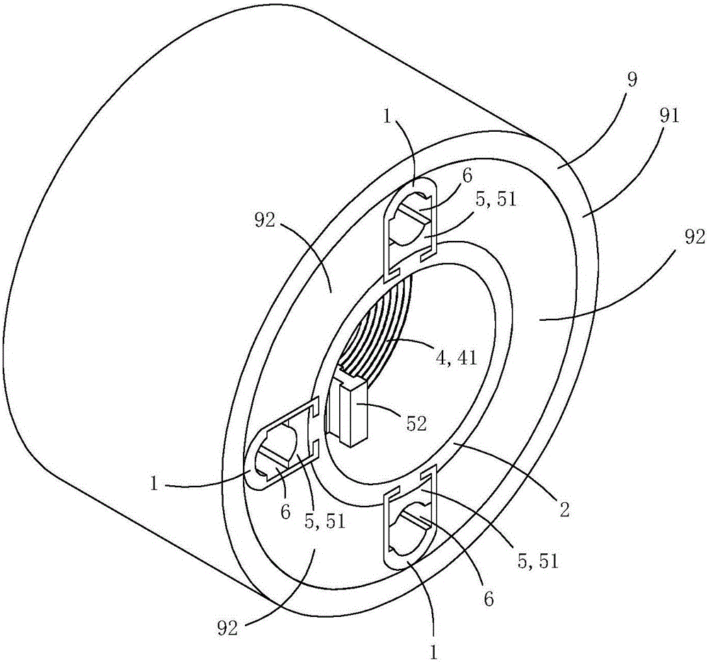
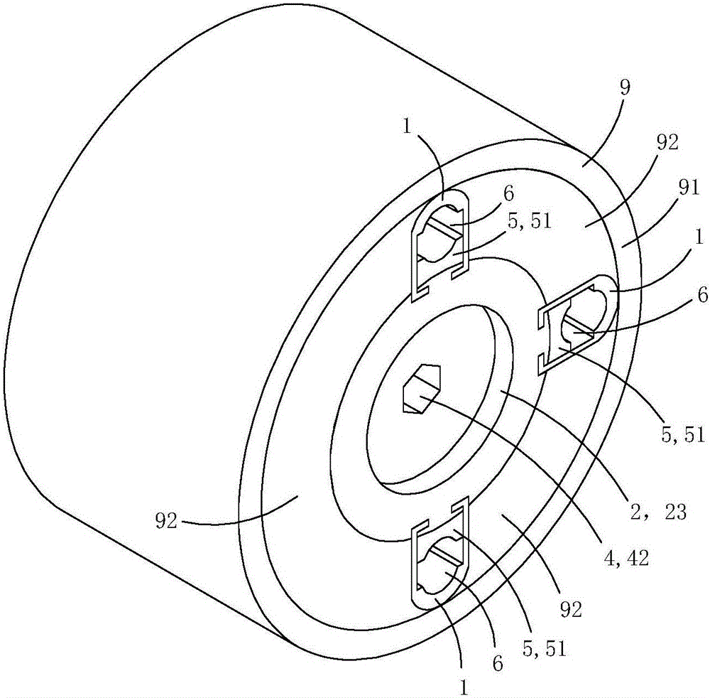
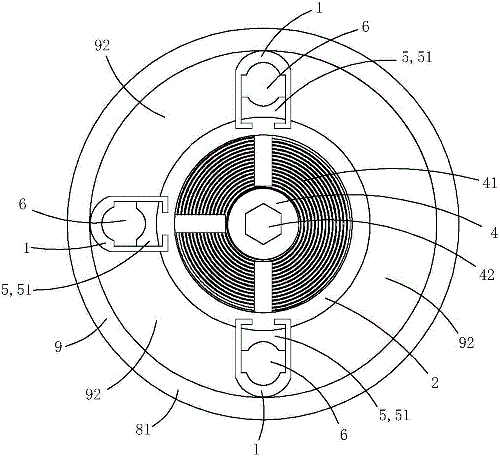
[0021] The present embodiment is a kind of power line connection clip, see Figure 1 to Figure 10 As shown, it includes a core tube 2 , a set of pressing jaw assembly 3 , a flat nut 4 , a current transformer 9 and three crimping parts 1 .

[0022] The tube wall of the core tube is provided with three radial limiting sliding holes 22, and each radial limiting sliding hole runs through the core tube tube wall along the radial direction of the core tube; each radial limiting sliding hole is located on the axial direction of the core tube. In the middle part, the radial cross-sectional shape of each radial limit hole is I-shaped; the inner peripheral wall of the core tube is provided with an inwardly protruding annular stopper 23 .

[0023] Each crimping piece is provided with a pressing plate portion 11 and an anti-off connecting portion 12; the crimping piece is detachably arranged on the core tube through the anti-off connecting portion; the pressing plate portion 11 extends ax...

Embodiment 2)

[0035] This embodiment is basically the same as the above-mentioned embodiment 1, the difference is that: see Figure 11 to Figure 13 As shown, the current transformer 9 in this embodiment includes a ring-shaped sensing body 91 and an intelligent control module 92; the overall shape of the smart control module is also ring-shaped; the ring-shaped sensing body 91 and the smart control module 92 are arranged side by side on the outer periphery of the crimping piece on the wall.

[0036] At least one of the crimping parts 1 is provided with a mounting screw hole 15 penetrating through the pressing plate portion in the radial direction of the core tube; a temperature sensing device 8 is fixed in the mounting screw hole.

[0037] The temperature sensing device 8 includes a metal housing 81 made of metal material with a containing groove 811, a temperature sensor 82 arranged in the containing groove, and a spring 83 for crimping the temperature sensor on the bottom wall of the conta...


PUM


Abstract

The invention discloses a three-phase high-voltage zero-sequence current transformer, which comprises a core tube, one set of press claw components, a flat nut, a current transformer body and three crimping parts, wherein each crimping part is provided with a press plate part and an anti-drop connection part; the crimping parts are detachably arranged on the core tube through the anti-drop connection parts respectively; the press plate parts are located at the outer side of the core tube; three radial limiting slide holes are formed in the tube wall of the core tube; the press claw components comprise three press claws; each press claw comprises a top plate part, a guide slide block part and a drive thread part; each guide slide block part is inserted into one corresponding radial limiting slide hole; the drive thread parts extend into a tube cavity of the core tube; the flat nut is rotationally arranged in the tube cavity of the core tube; the flat nut comprises a plane thread part; the current transformer body comprises an annular base body; the annular base body is located at the outer sides of the crimping parts; and a mounting screw hole of a built-in temperature sensing device is formed in at least one crimping part. The three-phase high-voltage zero-sequence current transformer has a real-time temperature monitoring function.

Description

technical field [0001] The invention belongs to the technical field of electric power, and in particular relates to a three-phase high-voltage zero-sequence current transformer. Background technique [0002] The basic principle of zero-sequence current protection is based on Kirchhoff's current law: the algebraic sum of the complex current flowing into any node in the circuit is equal to zero. When the line and electrical equipment are normal, the vector sum of the currents of each phase is equal to zero. Therefore, the secondary side winding of the zero-sequence current transformer has no signal output, and the actuator does not operate. When an electric shock or leakage fault occurs, the vector sum of the currents of each phase is not zero, and the fault current causes magnetic flux in the iron core of the zero-sequence current transformer, and the current generated by the zero-sequence current transformer is the zero-sequence current. When the protection mechanism receiv...

Claims


Application Information

Patent Timeline
IPC IPC(8): H01F27/06H01F38/38H01F27/40H02G7/04F16L3/10G01K7/22
CPCH01F27/06F16L3/10G01K7/22H01F27/402H01F38/38H01F2027/406H02G7/04
Inventor 胡妍
Owner 胡妍
Why Eureka
Try Eureka