Optical power control system, control method and laser Doppler velocimeter
An optical power control and optical power technology, applied in the field of laser Doppler velocimeters, can solve problems such as interference signal amplitude and baseline instability, oscilloscope test waveform over-screen, affecting test results, etc., to enhance the ability to transmit optical power , the effect of extending the test depth of field and improving the quality
- Summary
- Abstract
- Description
- Claims
- Application Information
AI Technical Summary
Problems solved by technology
Method used
Image

Examples
Embodiment 1
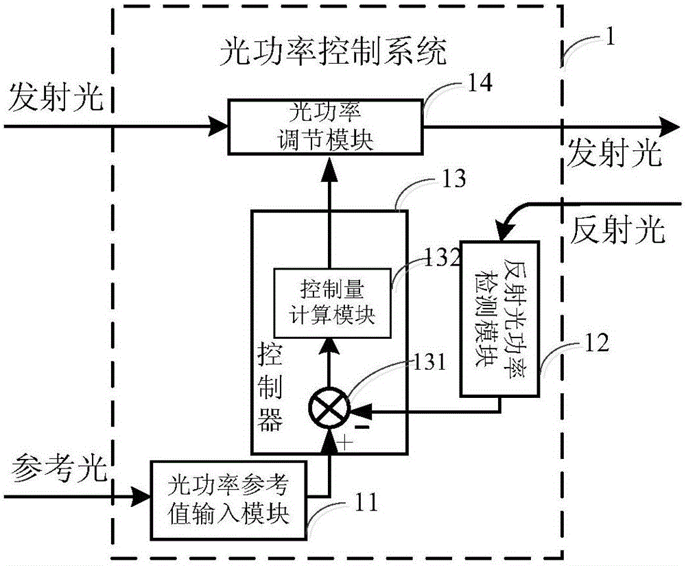
[0038] figure 1 It is a functional block diagram of the optical power control system provided by Embodiment 1 of the present invention. Such as figure 1 As shown, the optical power control system 1 includes an optical power reference input module 11 , a reflected optical power detection module 12 , a controller 13 , and an optical power adjustment module 14 . The controller 13 includes a difference module 131 and a control amount calculation module 132 . Specifically, the input end of the optical power adjustment module 14 receives the transmitted light, the input end of the optical power reference value input module 11 receives the reference light, the reflected optical power detection module 12 receives the reflected light, and the output end of the control amount calculation module 132 is connected to the optical power The electrical input end of the adjustment module is connected, an input end of the difference seeking module 131 is connected with the output end of the re...
Embodiment 2
[0045] Embodiment 2 provides an optical power control method, including the following steps.
[0046] Step (1): The optical power reference value input module receives the reference light emitted by the laser of the laser Doppler velocimeter and detects the reference optical power, converts the reference optical power information into an electrical signal and sends the electrical signal to the controller.
[0047] Step (2): The reflected light power detection module receives the reflected light and detects the reflected light power, converts the reflected light power information into an electrical signal, and sends the electrical signal to the controller;
[0048] Step (3): The controller calculates the difference between the reference optical power and the reflected optical power, calculates a control amount based on the difference in conjunction with a control algorithm, and sends the control amount to the optical power adjustment module. In this embodiment, the control algo...
Embodiment 3
[0051] Embodiment 3 provides a laser Doppler velocimeter, which includes the laser Doppler velocimeter optical power control system 1 in Embodiment 1.
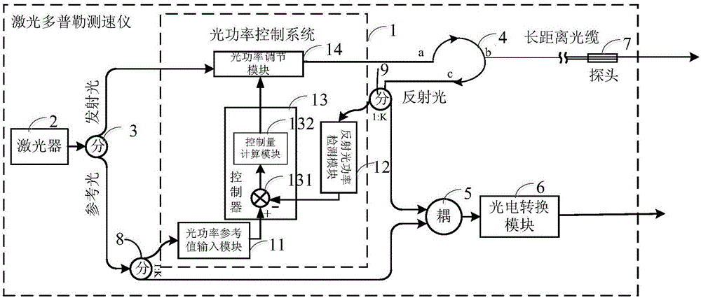
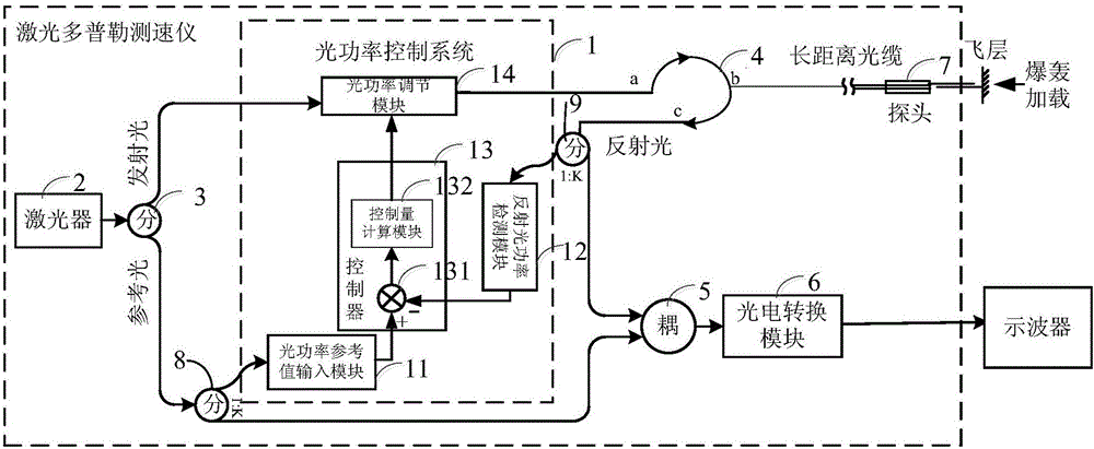
[0052] figure 2 The functional block diagram of the laser Doppler velocimeter provided for embodiment three, as figure 2 As shown, it includes the optical power control system 1 in Embodiment 1, which also includes a laser 2, a first optical splitter 3, a circulator 4, a coupler 5, a photoelectric conversion module 6, a probe 7, a second optical splitter 8, The third optical splitter 9, the output end of the laser 2 is connected with the input end of the first optical splitter 3, an output end of the first optical splitter 3 is connected with the input end of the second optical splitter 8, and an output of the second optical splitter 8 end is connected with the optical power reference value input module 11, the other output end of the second optical splitter 8 is connected with the coupler 5, the other output end of the fir...
PUM
 Abstract
Description
Claims
Application Information
 - R&D
- Intellectual Property
- Life Sciences
- Materials
- Tech Scout
- Unparalleled Data Quality
- Higher Quality Content
- 60% Fewer Hallucinations
Browse by: Latest US Patents, China's latest patents, Technical Efficacy Thesaurus, Application Domain, Technology Topic, Popular Technical Reports.
© 2025 PatSnap. All rights reserved.Legal|Privacy policy|Modern Slavery Act Transparency Statement|Sitemap|About US| Contact US: help@patsnap.com