Electrical Insulation Structure for Hall Thruster Gas Supply Line

A technology of Hall thruster and air supply pipeline, applied in thrust reverser, using plasma, machine/engine, etc., can solve problems such as insulation failure, and achieve the effect of good insulation performance, high reliability and improved insulation strength

Active Publication Date: 2018-07-03
HARBIN INST OF TECH
View PDF3 Cites 0 Cited by
  • Summary
  • Abstract
  • Description
  • Claims
  • Application Information

AI Technical Summary

Problems solved by technology

[0004] The invention aims to solve the problem of insulation failure caused by vacuum insulation surface flashover mechanism on the outside of the existing Hall thruster gas circuit insulator and insulation failure caused by low pressure breakdown mechanism on the inside of the insulator

Method used


Image

  • Electrical Insulation Structure for Hall Thruster Gas Supply Line
  • Electrical Insulation Structure for Hall Thruster Gas Supply Line
  • Electrical Insulation Structure for Hall Thruster Gas Supply Line

Examples


specific Embodiment approach 1

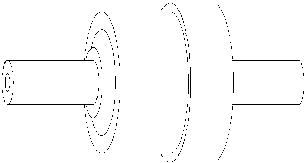
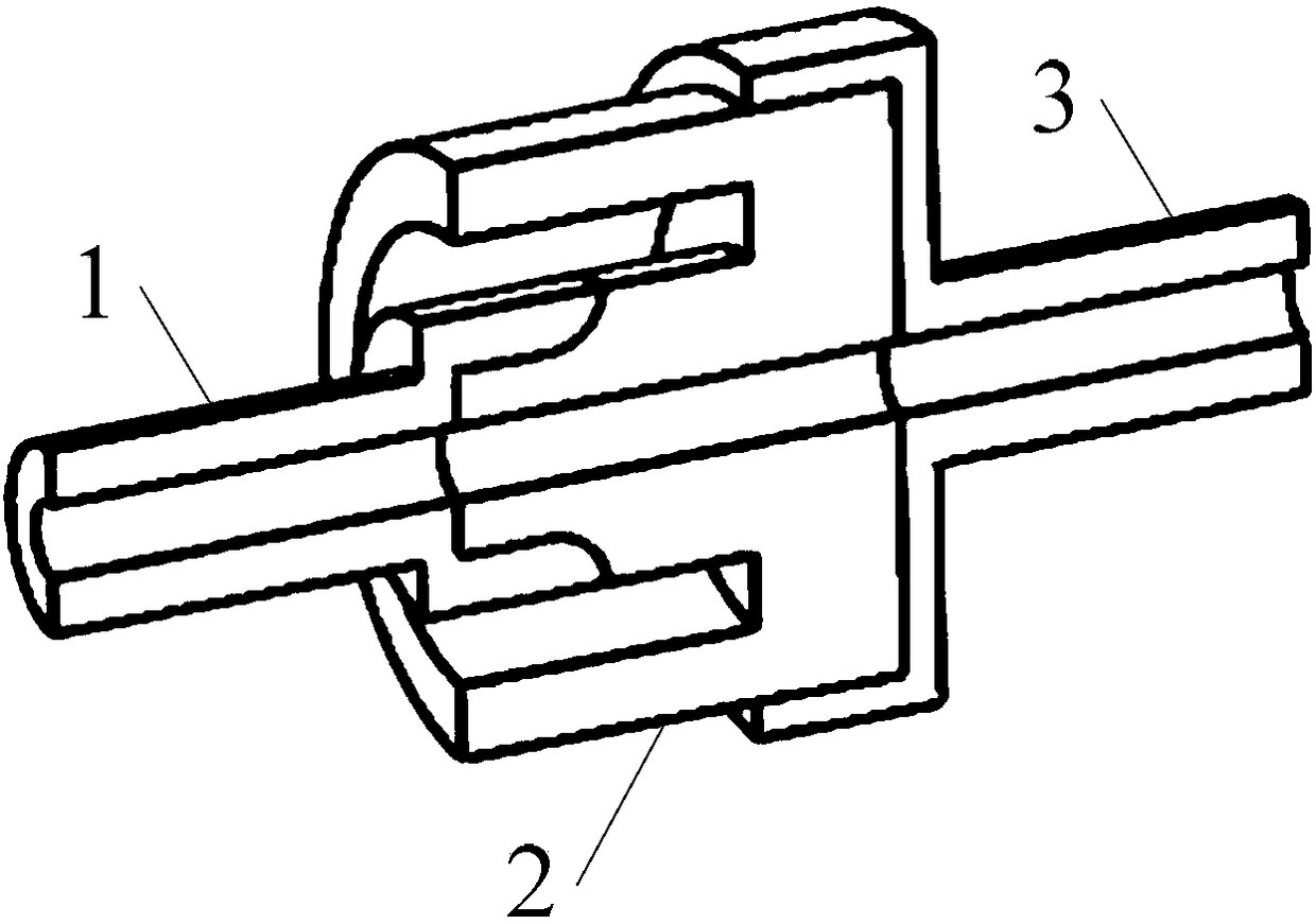
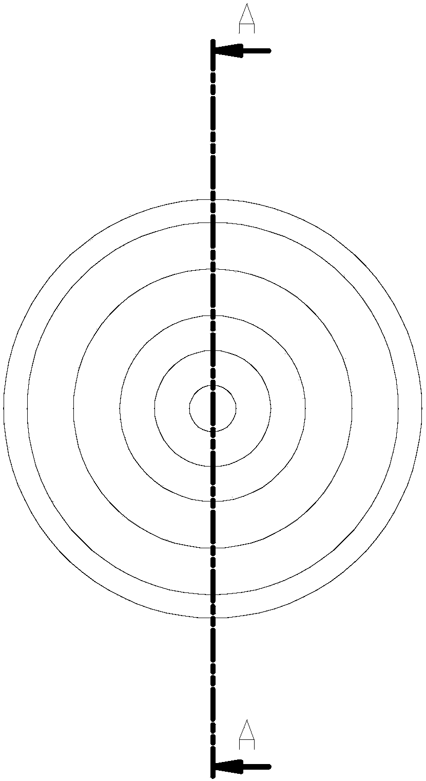
[0018] Specific implementation mode one: refer to Figure 1 to Figure 4 Describe this embodiment in detail, the electrical insulation structure used for the gas supply pipeline of the Hall thruster described in this embodiment, it includes a gas distributor pipeline 1, a ceramic insulator 2 and a metal port 3 of the storage and supply system,

[0019] The cross-section of the ceramic insulator 2 has a "mountain"-shaped structure, and the outer surface of the ceramic insulator 2 is a cylindrical structure, and the middle end of the ceramic insulator 2 is a convex groove structure.

[0020] The metal port 3 of the storage and supply system is wrapped on the bottom of the ceramic insulator 2, the groove structure of the gas distributor pipeline 1 is connected with the convex groove structure of the ceramic insulator 2, and the ceramic insulator 2 wraps the gas distributor pipeline 1,

[0021] The inner cavity of the gas distributor pipeline 1, the ceramic insulator 2 and the meta...

specific Embodiment approach 2

[0027] Specific embodiment 2: This embodiment is to further explain the electrical insulation structure used for the gas supply pipeline of the Hall thruster described in the specific embodiment 1. In this embodiment, the metal port 3 of the storage and supply system is connected to the bottom of the ceramic insulator 2 Brazed connections.

specific Embodiment approach 3

[0028] Embodiment 3: This embodiment is to further explain the electrical insulation structure used for the gas supply pipeline of the Hall thruster described in Embodiment 1. In this embodiment, the middle end of the ceramic insulator 2 and the gas distributor tube Way 1 solder connection.


PUM


Abstract

The invention relates to an electrical insulation structure used for a gas supply pipeline of a Hall thruster, relating to the electrical insulation field of an electric thruster. The invention aims to solve the problem of insulation failure caused by vacuum insulation surface flashover mechanism on the outside of the existing Hall thruster gas circuit insulator and insulation failure caused by low pressure breakdown mechanism on the inside of the insulator. The cross-section of the ceramic insulator of the present invention is a "mountain"-shaped structure, and the outer surface of the ceramic insulator is a cylindrical structure, and the middle end of the ceramic insulator is a convex groove structure. This structure greatly increases the length of the creepage channel in a limited space and reduces the The space plasma impacts the creepage channel under the action of the electrode electric field. At the same time, the gas distributor pipeline is wrapped in the ceramic insulator, which reduces the bombardment of charged particles on the insulator at high potential and high electric field strength, thereby improving The dielectric strength of the anti-vacuum flashover characteristics.

Description

technical field [0001] The invention relates to an insulation design mainly used for electrical insulation of an electric thruster, and the design can be used for the insulation of a gas supply pipeline in the electric thruster with a potential difference lower than 1000V. Background technique [0002] Compared with other electric propulsion devices, the Hall thruster has the advantages of simple structure, greater thrust, higher efficiency and reliability. After more than 40 years of theoretical research and practical application, the engineering research and design of the Hall thruster abroad have been very mature . At present, our country is in the stage of vigorously developing electric propulsion technology, and the research work on the engineering application of the Hall thruster is still in its infancy. Among them, it is extremely important to ensure the safety of the electrical insulation of the Hall thruster and ensure its high reliability. step. Different from th...

Claims


Application Information

Patent Timeline
Patent Type & Authority Patents(China)
IPC IPC(8): F03H1/00
CPCF03H1/0037
Inventor 丁永杰魏立秋李鸿于达仁
Owner HARBIN INST OF TECH
Why Eureka
Try Eureka