Detection device and detection control method

A technology for detection devices and detection areas, which can be used in instruments, televisions, optics, etc., and can solve problems such as inability to detect objects and troubles

Active Publication Date: 2019-08-27
CASIO COMPUTER CO LTD
View PDF4 Cites 0 Cited by
  • Summary
  • Abstract
  • Description
  • Claims
  • Application Information

AI Technical Summary

Problems solved by technology

[0004] However, in the technology disclosed in Patent Document 1 above, for example, there is a problem that even when the posture of the imaging device is changed from a horizontal state to a vertical state, since the position of the specified area in the imaging screen is fixed, the There are also cases in which the motion of the subject cannot be detected at the user's desired position
In addition, the above-mentioned Patent Document 1 describes that the position of the designated area can be set arbitrarily, but in the case of always detecting the movement of the subject at the position desired by the user, every time the posture of the imaging device is changed, Need to reset the position of the designated area and become troublesome

Method used


Image

  • Detection device and detection control method
  • Detection device and detection control method
  • Detection device and detection control method

Examples


Embodiment Construction

[0016] Hereinafter, specific embodiments of the present invention will be described using the drawings. However, the scope of the invention is not limited to the illustrated examples.

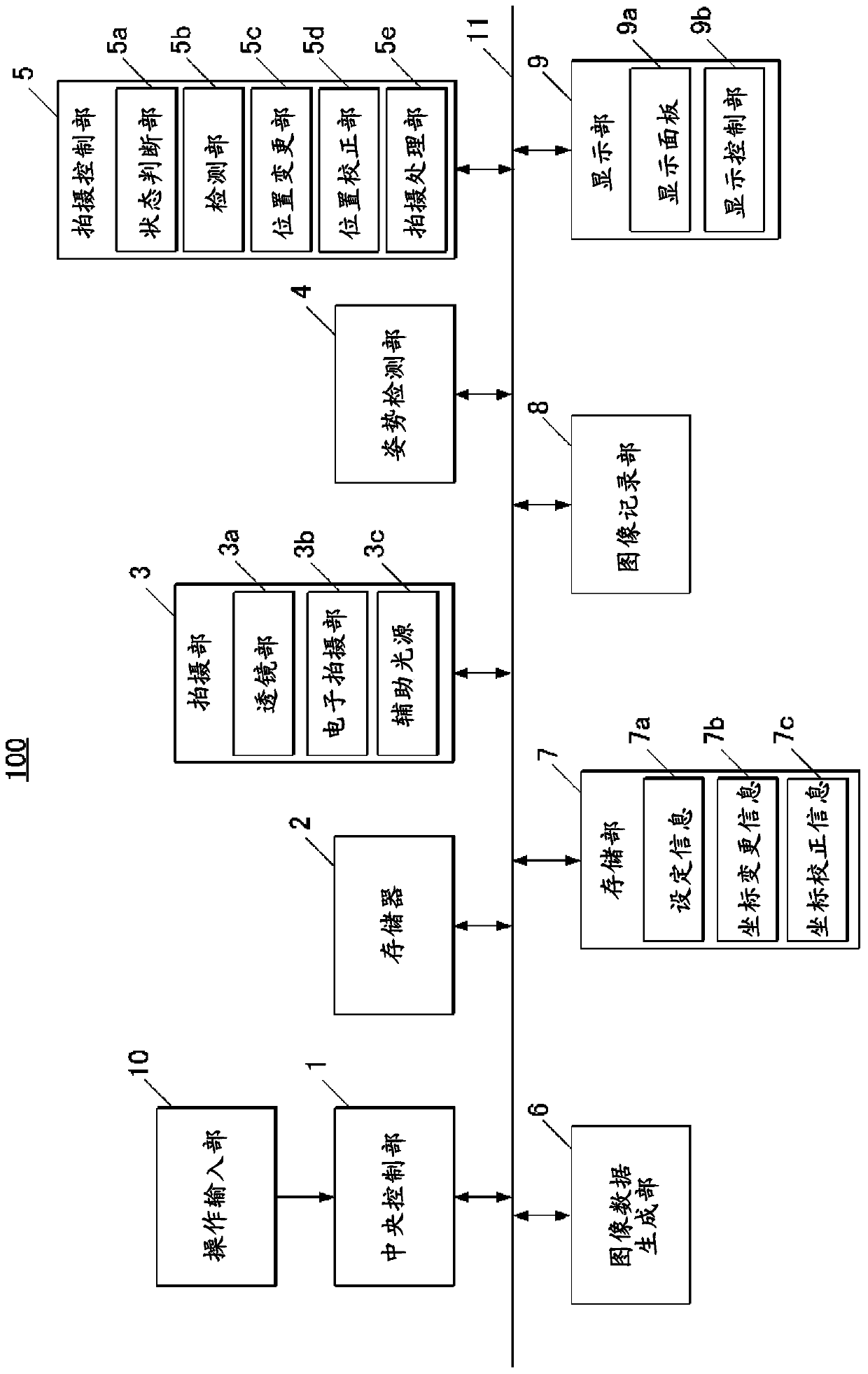
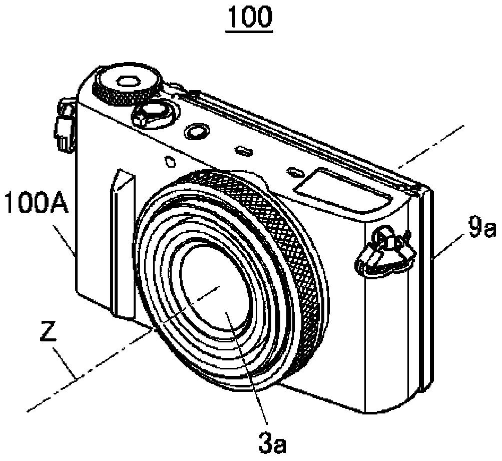
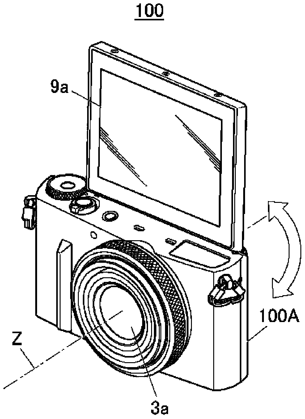
[0017] figure 1 It is a block diagram showing a schematic configuration of the imaging device 100 according to one embodiment of the present invention. in addition, Figure 2A is schematically shown figure 1 A perspective view of the photographing device 100, Figure 2B It is a perspective view schematically showing a state in which the display panel 9 a of the imaging device 100 is rotated by 180°.

[0018] like figure 1 As shown, the imaging device 100 of this embodiment includes a central control unit 1, a memory 2, an imaging unit 3, a posture detection unit 4, an imaging control unit 5, an image data generation unit 6, a storage unit 7, an image recording unit 8, and a display unit. 9 and the operation input unit 10.

[0019] In addition, the central control unit 1 , memory 2 , imag...


PUM


Abstract

The invention provides a detection device and a detection control method. An object of the present invention is to set a detection area for detecting a subject at a good position without wasting time when the posture of the device is changed. The imaging device (100) has: an imaging unit (imaging unit (3)); a posture detection unit (position detection unit (4)) that detects the posture of the imaging device (100); an object detection unit (detection unit (5b) ) that detects an object in a detection area (detection area (T) in the live view image (L)) within the captured image (live view image (L)) captured by the above-mentioned imaging unit; and a position changing unit (position A changing unit (5c)) that changes the position of the detection area in the captured image based on the posture of the imaging device (100) detected by the posture detection means.

Description

[0001] This application claims priority based on Japanese Patent No. 2015-013862 filed on January 28, 2015, and the entire content of the basic application is cited in this application. technical field [0002] The invention relates to a detection device and a detection control method. Background technique [0003] Conventionally, as a function provided in an imaging device such as a digital camera, for example, Japanese Patent Application Laid-Open No. 2005-333420, it is known to automatically close the shutter by detecting the movement of the subject in a designated area (detection area) within the imaging screen. automatic shooting function (hereinafter referred to as motion shutter). [0004] However, in the technology disclosed in Patent Document 1 above, for example, there is a problem that even when the posture of the imaging device is changed from a horizontal state to a vertical state, since the position of the specified area in the imaging screen is fixed, the The...

Claims


Application Information

Patent Timeline
Patent Type & Authority Patents(China)
IPC IPC(8): H04N5/225G03B15/00G06V10/22
CPCG03B15/00H04N23/531H04N23/58H04N23/63G06V40/166G06V30/142G06V10/242G06V10/22H04N23/667
Inventor 下野勉远藤将幸
Owner CASIO COMPUTER CO LTD
Why Eureka
Try Eureka