Optical cable transfer box and monitoring device and monitoring system thereof
A technology of optical cable transfer box and monitoring device, which is applied to measuring devices, measuring heat, and parts of thermometers, etc., can solve the problems of incomplete monitoring and high cost of monitoring devices, and achieve the effect of simple structure and low cost
- Summary
- Abstract
- Description
- Claims
- Application Information
AI Technical Summary
Problems solved by technology
Method used
Image
Examples
Embodiment 1
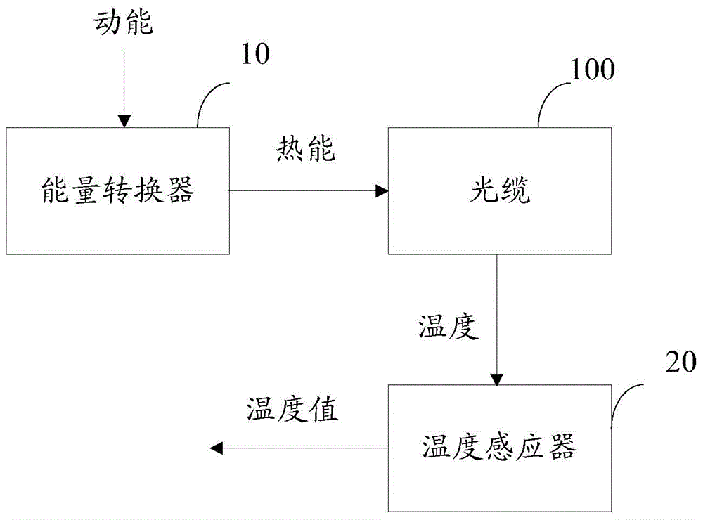
[0027] see figure 1 , an embodiment of the present invention provides a monitoring device for an optical cable transfer box, including:
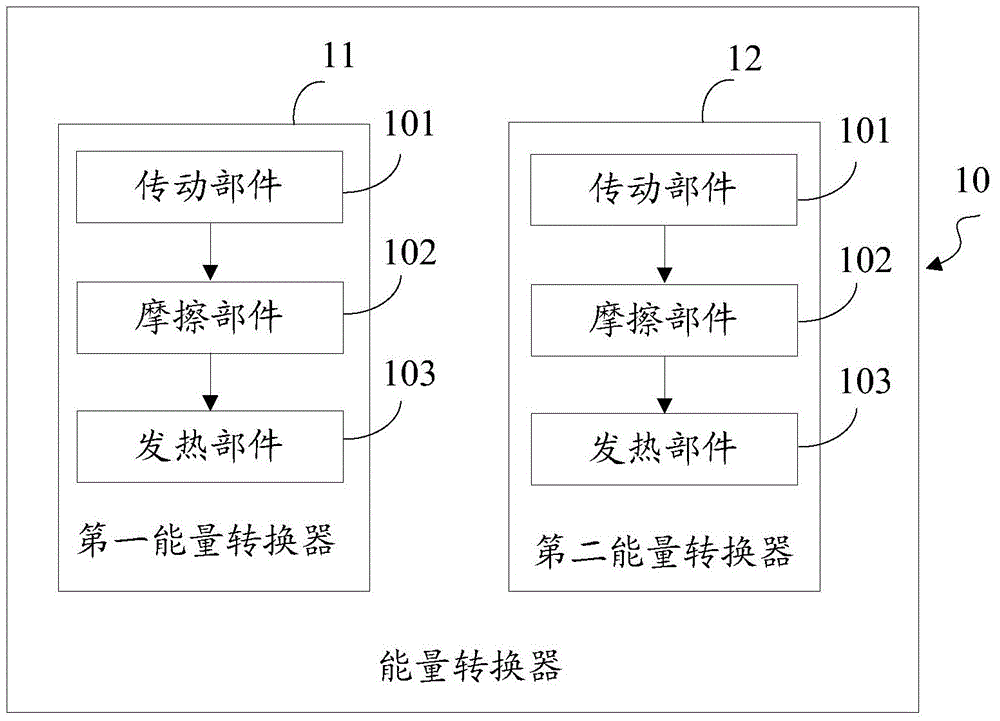
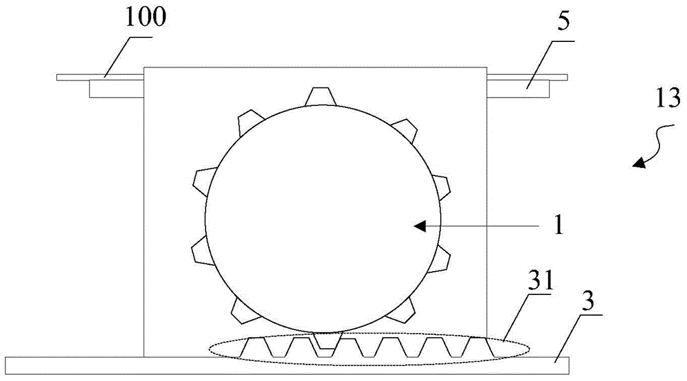
[0028] The energy converter 10 arranged in the box of the optical cable transfer box, the energy converter 10 is used for the kinetic energy generated during the opening or closing of the door of the optical cable transfer box and the kinetic energy generated when the optical cable transfer box is hit. The kinetic energy of the optical cable is converted into thermal energy, and the converted thermal energy is transferred to the optical cable 100 in the optical cable transfer box, so that the temperature of the optical cable 100 changes;
[0029] The temperature sensor 20 coupled to the optical cable, the temperature sensor 20 is used to sense the temperature of the optical cable 100, and send the temperature value sensed by the optical cable 100 to the remote end through the optical cable 100 alarm device (not shown).
[0030] In the embo...
Embodiment 2
[0052] An embodiment of the present invention provides an optical cable splicing box, including the monitoring device for the optical cable splicing box provided in the above embodiment.
[0053] The beneficial effects of the embodiments of the present invention are as follows: the optical cable transfer box uses the energy converter to convert kinetic energy, and uses the temperature value generated by the temperature sensor as a state parameter for monitoring the optical cable transfer box, which can simultaneously realize all The open or closed state of the door of the optical cable transfer box and the monitoring of the impact phenomenon of the optical cable transfer box, the monitoring device of the optical cable transfer box is simple in structure, does not need additional power supply, and has a low cost.
Embodiment 3
[0055] see Figure 7 The embodiment of the present invention provides a first optical cable transfer box monitoring system 200, including a plurality of the optical cable transfer box monitoring devices 201 provided in the above embodiment, and an alarm device 202 arranged at the remote end;
[0056] A plurality of the optical cable transfer box monitoring devices 201 are respectively arranged in a plurality of the optical cable transfer box, and the alarm device 202 is connected to the temperature sensor 20 of each of the optical cable transfer box monitoring devices 201 through the optical cable 100;
[0057] The energy converter 10 of the optical cable transfer box monitoring device 201 is used to convert the kinetic energy generated during the opening or closing of the door of the optical cable transfer box and the kinetic energy generated when the optical cable transfer box is hit into heat energy, And transfer the converted heat energy to the optical cable 100 in the opt...
PUM
 Abstract
Description
Claims
Application Information
 - R&D
- Intellectual Property
- Life Sciences
- Materials
- Tech Scout
- Unparalleled Data Quality
- Higher Quality Content
- 60% Fewer Hallucinations
Browse by: Latest US Patents, China's latest patents, Technical Efficacy Thesaurus, Application Domain, Technology Topic, Popular Technical Reports.
© 2025 PatSnap. All rights reserved.Legal|Privacy policy|Modern Slavery Act Transparency Statement|Sitemap|About US| Contact US: help@patsnap.com


